Bently Nevada 200155-06-05 Retrofit-Ready Vibration Accelerometer for TrendMaster Pro Control Systems
The Bently Nevada 200155-06-05 is a low-frequency vibration accelerometer engineered for seamless integration into legacy TrendMaster Pro continuous monitoring systems. As industrial facilities face increasing pressure to extend the operational life of existing machinery protection infrastructure, this accelerometer serves as a verified drop-in replacement for discontinued or end-of-life sensor assemblies within the TrendMaster Pro platform. Whether you are upgrading a rotating machinery protection loop, restoring a failed measurement channel, or migrating from an older Bently Nevada 3300 series rack to a modernized TrendMaster Pro architecture, the 200155-06-05 delivers the signal fidelity and mechanical compatibility required for uninterrupted plant operations.
Procurement engineers and reliability teams working on brownfield retrofit projects will find this unit particularly valuable when sourcing becomes critical. The 200155-06-05 is designed to interface directly with TrendMaster Pro I/O modules, including the standard dynamic input cards used for velocity and acceleration measurement across turbine, compressor, pump, and motor applications. Its connector pinout, cable shield grounding scheme, and sensitivity specification align with the original factory configuration, eliminating the need for signal conditioning rewiring or software scaling adjustments in the System 1 monitoring software.
Upgrade Compatibility Table
| Parameter | Details |
|---|---|
| Compatible Platform | Bently Nevada TrendMaster Pro |
| Replaces | 200155-06-05 (OEM), legacy low-frequency accelerometer variants |
| Mounting Interface | Standard stud mount, compatible with existing sensor brackets |
| Connector Type | 2-pin MIL-spec connector, matches TrendMaster Pro field wiring |
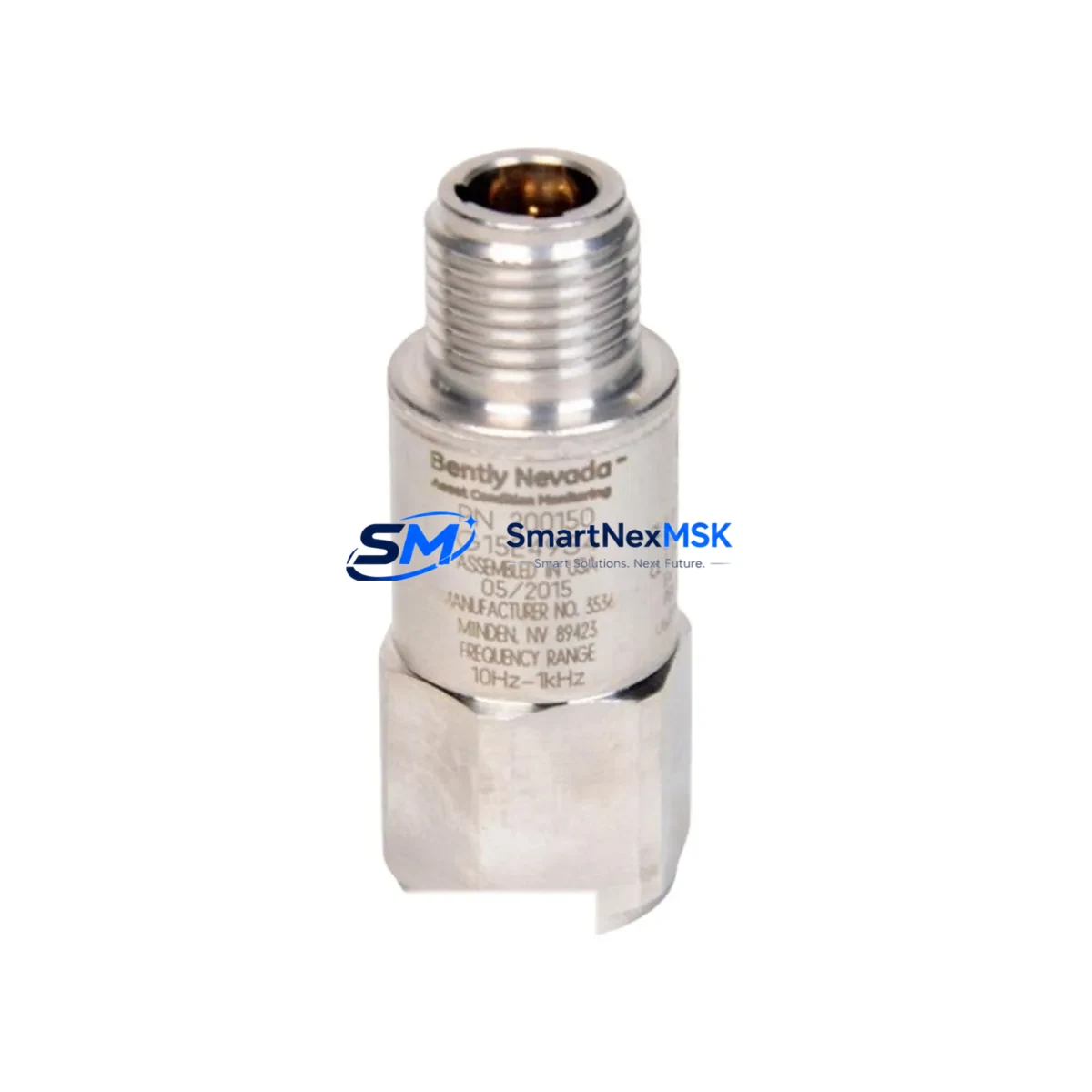
| Signal Output | IEPE / ICP® compatible, 100 mV/g nominal sensitivity |
| Frequency Range | Low-frequency, suitable for slow-speed machinery monitoring |
| Communication Compatibility | Passive analog; integrates with TrendMaster Pro dynamic I/O cards |
| Installation Requirement | No hardware modification required; direct field replacement |
| Retrofit Recommendation | Verify cable continuity and shield grounding before commissioning |
| Commissioning Note | Confirm channel sensitivity scaling in System 1 software post-installation |
| Warranty | 12 Months from date of shipment |
Retrofit Planning for Existing Automation Systems
Successful integration of the 200155-06-05 into a running TrendMaster Pro system requires a structured pre-installation review. Begin by auditing the existing TrendMaster Pro rack assembly, confirming the slot assignment of the dynamic input I/O module that services the affected measurement channel. In multi-rack configurations, the rack address and channel number must be documented before any physical swap to ensure the System 1 database mapping remains intact.
Field technicians should inspect the existing sensor cable for insulation integrity and verify that the Bently Nevada 3500/42M or equivalent proximitor power supply feeding the accelerometer loop is within specification. If the installation involves a mixed-platform cabinet where TrendMaster Pro I/O cards share a backplane with 3500 series modules, confirm that the power distribution within the control cabinet does not introduce ground loops that could corrupt the low-level analog signal from the 200155-06-05.
For facilities transitioning from older Bently Nevada 7200 series proximity probes or 330400 series accelerometers to the TrendMaster Pro architecture, the 200155-06-05 represents a compatible upgrade path that preserves existing conduit runs and junction box terminations. The terminal block wiring at the I/O module end should be verified against the TrendMaster Pro field wiring diagram, paying particular attention to the shield drain wire connection at the rack entry point.
In applications where the 200155-06-05 is being installed alongside a Bently Nevada 3500/22M transient data interface or a 3500/25 keyphasor module, ensure that the system configuration in System 1 software reflects the updated sensor type and sensitivity value. HMI display screens configured in System 1 Evolution or legacy System 1 Classic should be reviewed to confirm that alarm setpoints, trend displays, and dynamic data plots reference the correct engineering units following the sensor replacement. If the facility uses a DCS integration via Modbus or OPC-DA from the TrendMaster Pro gateway, verify that the tag mapping for the affected channel remains consistent after the swap to avoid false alarms at the control room level.
Technicians performing the physical installation should also confirm that the Bently Nevada 330130 or 330180 series extension cable connecting the accelerometer to the nearest junction box is undamaged and properly routed away from high-voltage conduits. Where cable replacement is necessary, the new cable assembly must match the original capacitance specification to maintain signal integrity across the full frequency range of the 200155-06-05.
Downtime Control During System Migration
Minimizing unplanned downtime during a TrendMaster Pro sensor replacement requires a disciplined hot-swap protocol. Where the monitoring system supports channel bypass or inhibit functions, activate the bypass for the affected channel in System 1 before disconnecting the field sensor. This prevents nuisance trips or spurious alarms from propagating to the DCS or safety instrumented system during the physical swap.
Retain a backup copy of the TrendMaster Pro configuration database and the System 1 machine train template before making any changes. If the replacement involves updating the I/O module firmware or reconfiguring the dynamic input card, perform these steps during a planned maintenance window rather than during live production. For critical machinery such as steam turbines or centrifugal compressors, coordinate the sensor swap with the operations team to align with a scheduled slow-roll or coast-down event, allowing the new 200155-06-05 to be verified under controlled conditions before returning the machine to full load.
Post-installation, perform a bench-level signal check by applying a known vibration reference to the accelerometer and confirming the output voltage at the I/O module terminal. Compare the live reading in System 1 against the expected value based on the 100 mV/g sensitivity of the 200155-06-05. Once the channel reading is confirmed stable and within the normal baseline band for the monitored machine, remove the channel inhibit and restore full monitoring coverage. Document the replacement in the plant maintenance management system with the new sensor serial number, installation date, and post-commissioning vibration baseline values.
Retrofit Support FAQ
Q1: Is the 200155-06-05 a direct replacement for the original Bently Nevada accelerometer in TrendMaster Pro systems?
Yes. The 200155-06-05 is designed as a form-fit-function replacement for the original low-frequency accelerometer used in TrendMaster Pro continuous monitoring applications. No modifications to the existing field wiring, conduit, or I/O module configuration are required for a standard replacement.
Q2: What commissioning steps are required after installing the 200155-06-05?
After physical installation, verify the cable shield grounding, confirm the channel sensitivity scaling in System 1 software, and perform a live signal check against a known vibration reference. Review HMI alarm setpoints and DCS tag mappings to ensure continuity with pre-replacement baseline values.
Q3: Can the 200155-06-05 be used in systems that also include Bently Nevada 3500 series modules?
Yes. In mixed-platform cabinets where TrendMaster Pro and 3500 series modules coexist, the 200155-06-05 can be installed on the TrendMaster Pro dynamic input channels without affecting adjacent 3500 series measurement loops, provided that power distribution and grounding within the control cabinet are properly segregated.
Q4: What warranty coverage is provided, and is pre-shipment testing performed?
All units are covered by a 12-month warranty from the date of shipment. Each 200155-06-05 undergoes functional verification and output signal testing prior to dispatch to confirm sensitivity, frequency response, and connector integrity. A test report is available upon request for critical replacement applications.
© 2026 SMARTNEXMSK. All rights reserved.
Original Source: https://smartnexmsk.com
Contact: sales@smartnexmsk.com | +86 18259474341


