Bently Nevada 200350-02-00-00 Spare for 3500 Automation: Precision Spare Parts Replacement for Vibration Monitoring Downtime Control
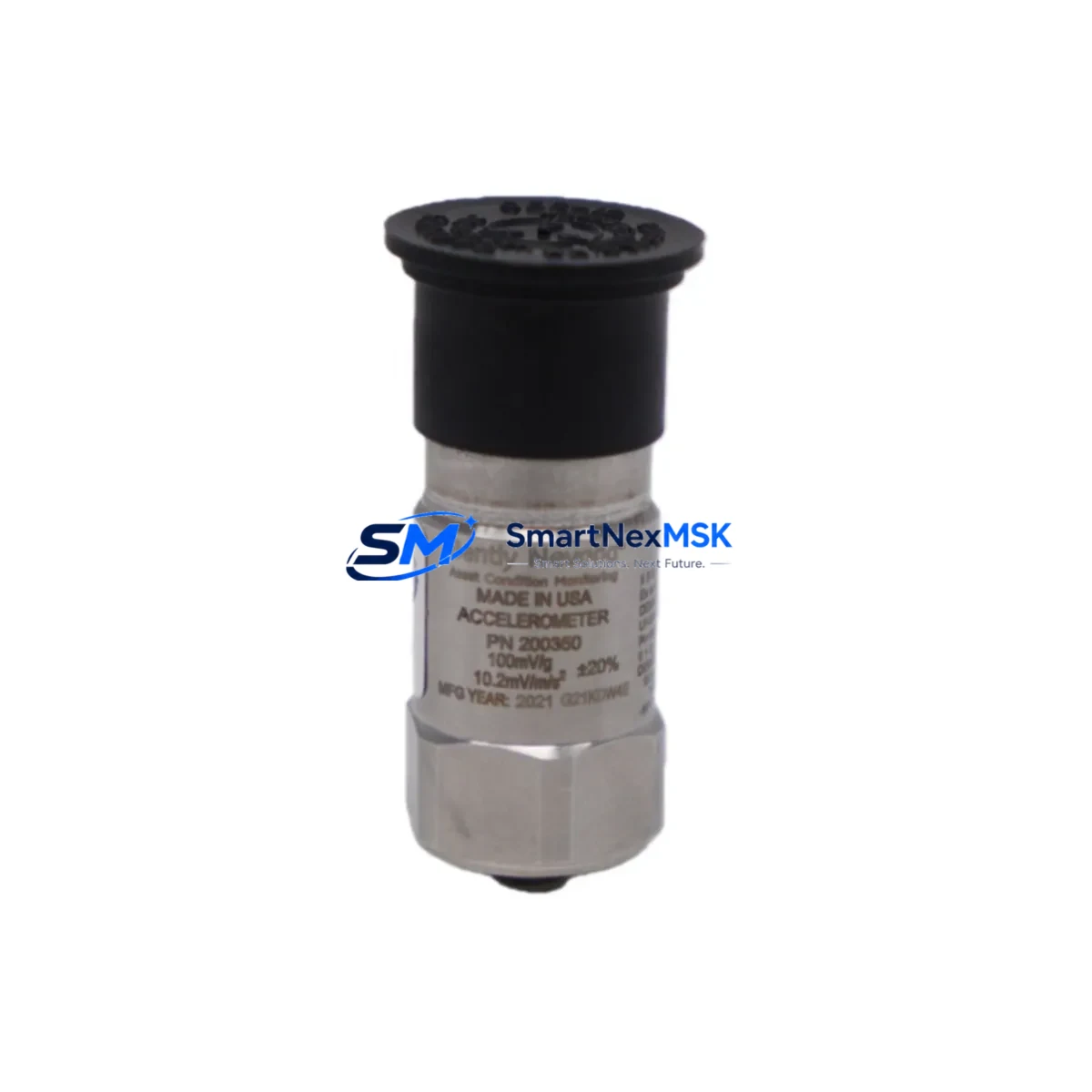
The Bently Nevada 200350-02-00-00 is a seismic accelerometer designed for use within the Bently Nevada 3500 Series machinery protection system — one of the most widely deployed continuous vibration monitoring platforms in rotating equipment facilities worldwide. When this sensor fails or degrades, the consequences extend beyond a single measurement point: the entire protection loop for a critical asset — compressor, turbine, pump, or motor — may be compromised, triggering unplanned shutdowns or, worse, masking developing faults.
This listing provides a maintenance-ready, original-specification replacement for the 200350-02-00-00 accelerometer. Each unit is sourced through verified industrial supply channels, functionally tested prior to dispatch, and backed by a 12-month warranty covering manufacturing defects and performance conformance. Fast lead times support both planned maintenance windows and emergency breakdown recovery scenarios.
Spare Maintenance Table
| Parameter | Specification / Detail |
|---|---|
| Part Number / SKU | 200350-02-00-00 |
| Brand | Bently Nevada |
| Series | 3500 Series Machinery Protection System |
| Product Type | Seismic Accelerometer (Vibration Transducer) |
| Sensor Output | Voltage output, compatible with 3500/42M and 3500/42E vibration monitor modules |
| Measurement Type | Absolute casing vibration (seismic / velocity) |
| Mounting | Stud-mount or adhesive mount per installation drawing |
| Operating Temperature | -40°C to +121°C (typical industrial range) |
| Connector / Interface | Compatible with standard Bently Nevada field wiring and junction box terminations |
| Application Environment | Rotating machinery: gas turbines, steam turbines, centrifugal compressors, pumps, motors |
| Compatibility | Bently Nevada 3500 Series rack-based protection system; replaces legacy 200350 variants |
| Origin | USA (Bently Nevada / Baker Hughes manufacturing) |
| Pre-shipment Testing | Functional output verification and sensitivity check performed before dispatch |
| Warranty | 12 Months — covers manufacturing defects and performance conformance |
| Lead Time | In-stock units ship within 1–3 business days; expedited options available |
| Maintenance Recommendation | Inspect every 12–18 months or at major turnaround; replace if sensitivity drift exceeds ±10% |
Maintenance Planning for Continuous Operation
Replacing the 200350-02-00-00 accelerometer is rarely an isolated task. Maintenance engineers performing a planned replacement or responding to a vibration channel fault should treat this as an opportunity to audit the full measurement chain and associated protection infrastructure. A systematic approach significantly reduces the risk of repeat failures and unplanned outages.
Begin with the 3500/42M or 3500/42E Vibration Monitor Module — the rack card that processes the accelerometer signal. Verify that the module’s input configuration matches the sensor type and that no channel faults or OK relay trips are latched. If the module has been in service for more than five years, consider scheduling it for bench calibration or replacement during the same window.
Next, inspect the field wiring and junction box terminations. Seismic accelerometers are sensitive to ground loops and cable shield integrity. Check the 3500/20 Rack Interface Module (RIM) for communication status and confirm that the rack is receiving clean power from the 3500/15 Power Supply Module — a failing power supply is a common root cause of spurious vibration alarms that are misdiagnosed as sensor faults.
For facilities running dual-redundant protection architectures, verify that the 3500/22M Transient Data Interface is logging correctly and that the System 1 Evolution software (or equivalent condition monitoring platform) is receiving valid data on all channels. A sensor swap is the right moment to confirm that the historian is capturing baseline vibration signatures for trend analysis.
If the machine being protected is a gas turbine or high-speed compressor, also review the status of any 3500/40M Proximitor / Seismic Monitor channels monitoring shaft relative vibration — these proximity probes and their 3300 XL 8mm or 3300 XL 11mm Proximitor Sensors operate in parallel with the seismic channel and should be cross-checked during the same inspection. Confirm that Keyphasor® module signals are clean and that phase reference is stable, as this affects both protection logic and diagnostic accuracy.
Finally, review the 3500/32 Relay Module output wiring to the DCS or safety system. Confirm that the relay trip setpoints have not drifted and that the overall vibration protection loop — from sensor to relay to DCS input card — is functioning as a validated, tested chain. Documenting this full-loop verification in the maintenance management system supports both regulatory compliance and long-term asset reliability.
Site Replacement Workflow
Step 1 — Identify and Isolate: Confirm the channel assignment of the 200350-02-00-00 in the 3500 rack configuration. Bypass the protection channel in the 3500/32 Relay Module per your site bypass procedure before disconnecting the sensor. Never remove a live sensor from an unbypassed protection loop on a running machine.
Step 2 — Remove and Inspect: Disconnect the field cable at the junction box. Remove the accelerometer from its mounting stud or adhesive pad. Inspect the mounting surface for corrosion, thread damage, or contamination. Clean and re-prepare the surface before installing the replacement unit.
Step 3 — Install Replacement: Mount the new 200350-02-00-00 per the original installation drawing. Torque the stud mount to specification. Reconnect the field cable, ensuring correct shield grounding at one end only to prevent ground loops.
Step 4 — Verify and Commission: Remove the bypass. Observe the channel output in the 3500 rack display or System 1 software. Confirm that the OK status is green, the vibration reading is within expected baseline range, and no alarms are active. Record the as-left reading in the maintenance log.
Step 5 — Update Spare Parts Inventory: Log the replaced unit’s serial number and installation date. Replenish your on-site spare stock to maintain at least one 200350-02-00-00 in reserve for the next unplanned event. For critical machines, a two-unit buffer is recommended given the potential cost of a single unplanned shutdown.
Spare Parts Support FAQ
Q1: Is this a genuine Bently Nevada 200350-02-00-00 or an aftermarket equivalent?
This unit is sourced to original Bently Nevada specifications. Each unit undergoes functional output and sensitivity verification before shipment. If you require OEM factory-new certification, please contact us with your project documentation and we will advise on availability and lead time.
Q2: What does the 12-month warranty cover?
The 12-month warranty covers manufacturing defects and performance non-conformance under normal operating conditions. It does not cover damage resulting from incorrect installation, overvoltage, mechanical impact, or operation outside the specified environmental range. Warranty claims are supported with a replacement unit dispatched after fault confirmation.
Q3: Can this unit replace older 200350 variants in my existing 3500 rack?
The 200350-02-00-00 is designed as a direct replacement within the 3500 Series architecture. For installations using earlier 200350 suffix variants, verify connector pinout and cable compatibility before installation. Our technical team can assist with cross-reference confirmation if you provide your rack configuration details.
Q4: How do you handle urgent breakdown orders?
In-stock units are dispatched within 1–3 business days under standard lead times. For breakdown emergencies, contact us directly at sales@smartnexmsk.com or +86 18259474341 to discuss expedited shipping options. We maintain buffer stock of high-demand 3500 Series components specifically to support unplanned maintenance events.
© 2026 SMARTNEXMSK. All rights reserved.
Original Source: https://smartnexmsk.com
Contact: sales@smartnexmsk.com | +86 18259474341


