Bently Nevada 21000-16-05-00-030-04-02 3500 Retrofit Module: Compatible Modernization for Legacy Vibration Monitoring Systems
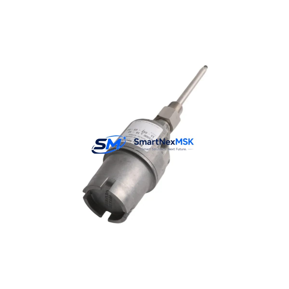
The Bently Nevada 21000-16-05-00-030-04-02 is a proximity transducer interface module designed for the Bently Nevada 3500 Series machinery protection system. As aging 3500 racks approach end-of-support cycles and OEM spare parts become increasingly scarce, this module serves as a critical retrofit-ready replacement for facilities managing rotating machinery — including turbines, compressors, pumps, and gearboxes — where continuous vibration monitoring is non-negotiable.
This module interfaces directly with Bently Nevada proximity transducer systems, accepting signals from standard 3300 XL 8mm and 11mm proximity probes and extension cables. It is engineered to slot into existing 3500/22M or 3500/42M rack positions without requiring backplane modifications, preserving your existing wiring harness and terminal block assignments. For engineers managing a brownfield upgrade, this compatibility eliminates the need for full rack replacement and dramatically reduces both engineering hours and scheduled downtime.
Upgrade Compatibility Table
| Parameter | Details |
|---|---|
| Compatible Rack | Bently Nevada 3500/20 Rack Interface Module, 3500/22M, 3500/42M |
| Replaces / Upgrades | Legacy 3500 proximity interface cards; discontinued 7200 Series transducer modules |
| Backplane Interface | Standard 3500 Series backplane — no hardware modification required |
| Communication Compatibility | Compatible with 3500/92 Communication Gateway (Modbus, Ethernet/IP) |
| Installation Requirement | Standard 3500 rack slot; verify slot addressing via rack configuration software |
| Transducer Input | Bently Nevada 3300 XL 8mm / 11mm proximity probes and extension cables |
| Retrofit Recommendation | Direct slot-in replacement; confirm I/O channel mapping before power-up |
| Commissioning Focus | Gap voltage verification, OK relay logic, alert/danger setpoint re-entry |
| Warranty | 12 months from date of shipment |
Retrofit Planning for Existing Automation Systems
Successful integration of the 21000-16-05-00-030-04-02 into an existing 3500 system requires a structured pre-installation review. Begin by auditing the 3500/20 Rack Interface Module to confirm available slot positions and current rack configuration. If the rack is operating at full capacity, a secondary rack expansion using a 3500/05 Power Supply may be required to support additional module loads without compromising system stability.
Terminal block wiring should be verified against the original I/O drawing package. The proximity probe circuit — comprising the probe tip, 3300 XL extension cable, and 3300 XL proximitor/oscillator — must be inspected for continuity and gap voltage compliance before the new module is energized. Any deviation in gap voltage (typically –10 VDC ±0.5 V) will trigger an OK relay fault and prevent the channel from entering monitoring mode.
For facilities also upgrading their communication infrastructure, the 3500/92 Communication Gateway Module supports Modbus RTU, Modbus TCP, and Ethernet/IP protocols, enabling integration with modern DCS platforms and SCADA systems. If your control room is migrating from a legacy Bently Nevada 3300 Series system to the 3500 platform, the communication gateway becomes a critical bridge between old historian data paths and new network-based monitoring architectures.
Where HMI screens are involved, operators should update vibration channel tag assignments in the System 1 Evolution condition monitoring software or equivalent historian to reflect the new module’s channel addressing. Failure to update tag mappings will result in stale or missing data on operator displays, even if the physical module is functioning correctly. Coordinate with your DCS or SCADA team to validate that all analog output signals — typically 4–20 mA — are correctly received at the 3500/42M Four-Channel Proximitor/Seismic Monitor or equivalent downstream device.
In multi-rack configurations, also verify the 3500/25 Enhanced Keyphasor Module timing reference is correctly shared across all racks. Phase reference errors introduced during a module swap can corrupt speed and phase measurements across the entire monitoring system, leading to false alerts during the post-installation verification run.
Downtime Control During System Migration
Minimizing unplanned downtime during a 3500 module replacement requires a disciplined hot-swap and bypass protocol. Where the rack supports it, place the affected channel into bypass mode via the rack configuration software before physically removing the legacy module. This prevents the OK relay from triggering a plant-level shutdown interlock while the slot is unpowered.
Retain a full backup of the rack configuration file — exported from Rack Configuration Software (RCS) — before any hardware change. This file contains all setpoint values, transducer scale factors, full-scale ranges, and relay logic assignments. If the replacement module requires re-programming, this backup eliminates the need to reconstruct configuration from paper records, which is a common source of commissioning errors in time-pressured outage windows.
After installation, perform a staged power-up: energize the rack, confirm the module’s OK LED status, verify gap voltage on each channel, and re-enter alert and danger setpoints before releasing the channel from bypass. Document all as-found and as-left values for the maintenance record. This sequence typically allows a single-module swap to be completed within a two-to-four hour maintenance window, even in facilities with strict change-control procedures.
For critical machinery where zero-downtime replacement is required, consider maintaining a pre-configured spare module — programmed and tested offline — so that the field swap is limited to physical installation and gap voltage verification only.
Retrofit Support FAQ
Q: Is the 21000-16-05-00-030-04-02 a direct drop-in replacement for my existing 3500 proximity interface card?
A: Yes, in most 3500 rack configurations this module occupies a standard slot and uses the existing backplane interface. Confirm your rack’s slot addressing and I/O channel mapping in RCS before installation to ensure a seamless swap.
Q: What wiring changes are required during installation?
A: In a like-for-like replacement, no wiring changes are typically required. The terminal block assignments for the proximity probe, extension cable, and proximitor connections remain identical. If you are upgrading from a 7200 Series or 3300 Series module, terminal re-mapping will be necessary — consult the 3500 Field Wiring Diagram for your specific rack model.
Q: How do I verify the module is functioning correctly after installation?
A: Confirm the OK LED is illuminated on the module front panel, verify gap voltage is within the –10 VDC ±0.5 V specification for each channel, and check that vibration amplitude and phase readings are consistent with pre-swap baseline values in System 1 or your SCADA historian. All modules are bench-tested and function-verified prior to shipment.
Q: What does the 12-month warranty cover?
A: The 12-month warranty covers manufacturing defects and functional failures under normal operating conditions from the date of shipment. Each unit undergoes pre-shipment functional testing. Warranty claims are supported directly — contact our technical team with your order reference and fault description for rapid resolution.
© 2026 SMARTNEXMSK. All rights reserved.
Original Source: https://smartnexmsk.com
Contact: sales@smartnexmsk.com | +86 18259474341


