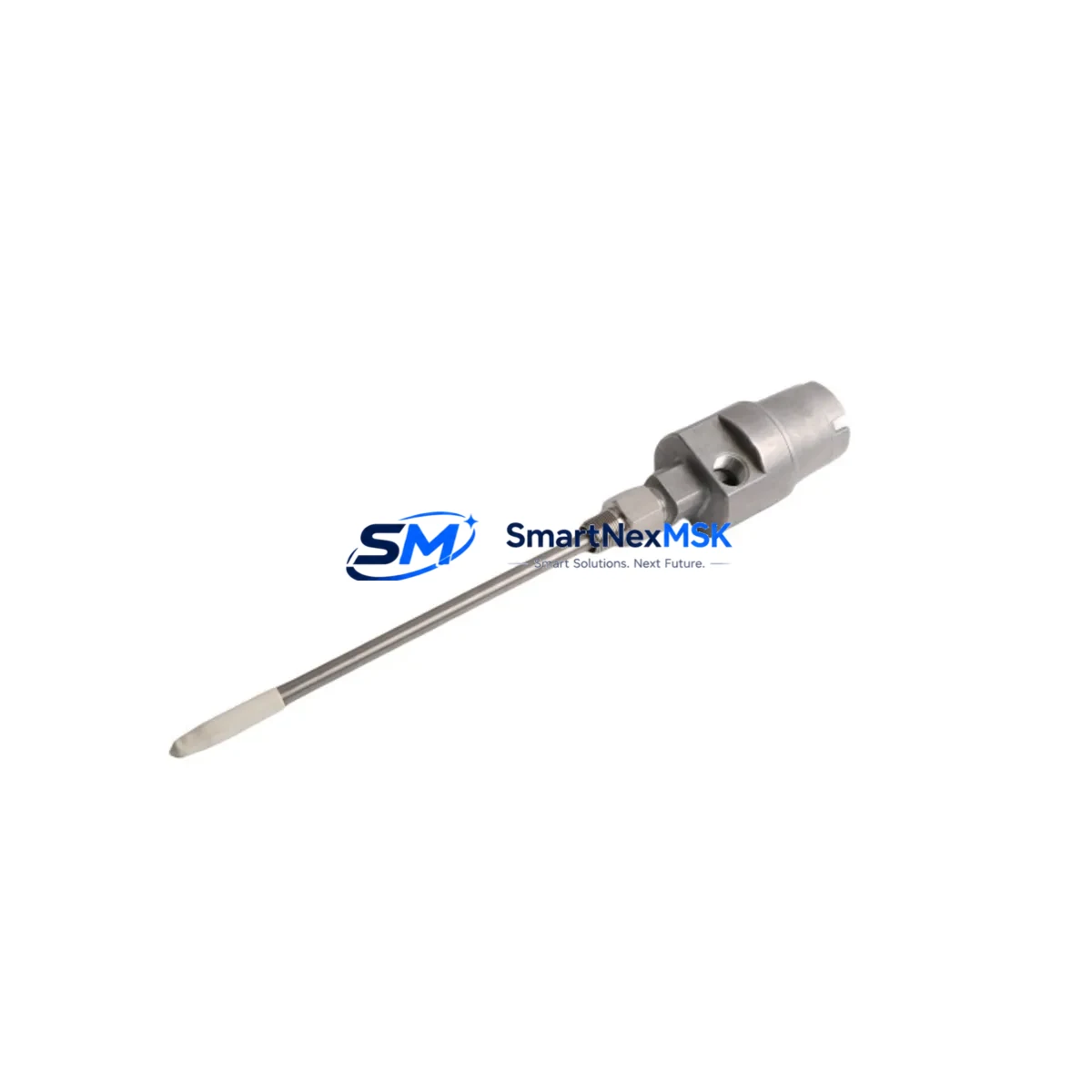
Bently Nevada 21000-16-05-00-038-04-02 Retrofit-Ready Proximity Probe Housing for 3300 XL Control Systems
The Bently Nevada 21000-16-05-00-038-04-02 is a precision proximity probe housing assembly engineered for the 3300 XL Series vibration monitoring platform. As legacy turbomachinery protection systems approach end-of-support cycles, this component serves as a verified drop-in replacement for aging or discontinued probe housings in rotating equipment monitoring applications — including steam turbines, gas compressors, centrifugal pumps, and large induction motors. Whether you are executing a planned outage upgrade, responding to a field failure, or building a critical spare inventory, this assembly delivers the dimensional accuracy, material specification, and signal integrity required for seamless integration into existing 3300 XL monitor racks.
The 21000-16-05-00-038-04-02 housing is designed to accept standard Bently Nevada eddy-current probe tips and extension cables, maintaining the gap voltage calibration curves expected by the 3300 XL 16-channel monitor and associated 3300/16 I/O modules. Replacement does not require recalibration of the full monitoring chain when the probe tip, extension cable, and driver remain unchanged — a critical advantage when minimizing downtime during a hot-standby switchover or a scheduled turnaround.
Upgrade Compatibility Table
| Parameter | Detail |
|---|---|
| SKU / Part Number | 21000-16-05-00-038-04-02 |
| Brand | Bently Nevada |
| Compatible Platform | 3300 XL Series Vibration Monitoring System |
| Component Type | Proximity Probe Housing Assembly |
| Probe Tip Compatibility | Standard Bently Nevada 3300 XL eddy-current probe tips (3300 XL NSv, 3300 XL 8mm) |
| Extension Cable Interface | Compatible with 3300 XL armored extension cables; standard BNC/coaxial termination |
| Mounting / Installation | Direct retrofit into existing probe bracket; no machining required for standard installations |
| Signal Output | Maintains –200 mV/mil (–7.87 V/mm) sensitivity curve when paired with original driver |
| Communication Compatibility | Passive analog signal; compatible with 3300 XL monitor rack Keyphasor and radial vibration channels |
| Replacement Recommendation | Direct replacement for worn, damaged, or discontinued 21000-series housings in 3300 XL installations |
| Commissioning Notes | Verify gap voltage (–10 VDC nominal at 50 mil gap) after installation; confirm OK/NOT OK relay logic in monitor |
| Warranty | 12 Months from date of shipment |
| Origin | USA (Bently Nevada / Baker Hughes) |
Retrofit Planning for Existing Automation Systems
A successful retrofit of the 21000-16-05-00-038-04-02 into an operating turbomachinery protection system requires a structured pre-outage assessment. Begin by auditing the existing probe chain: confirm the probe tip model (typically a Bently Nevada 3300 XL NSv Proximity Probe or 3300 XL 8mm Proximity Probe), the extension cable length and part number, and the driver/oscillator model installed in the field junction box. The housing replacement is mechanically straightforward, but the surrounding components must be verified to ensure the complete transducer system remains within the calibrated range of the 3300 XL Proximitor Sensor.
At the monitor rack level, confirm that the target channel on the 3300/16 Monitor is configured for the correct transducer type and sensitivity. If the installation includes a 3300 XL Keyphasor Module for phase reference, verify that the Keyphasor gap and trigger level settings are undisturbed during the housing swap. For systems using a 3500 Series rack as a migration target — a common upgrade path from older 3300 XL installations — note that the 3500/42M Proximitor I/O Module accepts the same probe chain, simplifying the transition without requiring new field wiring.
Power supply integrity is a prerequisite for any probe replacement. The 3300 XL Power Supply Module must deliver stable –24 VDC to the Proximitor circuit; measure supply voltage at the field terminal block before and after the swap. If the installation uses a 3300 XL Dual Power Supply configuration, confirm that the redundant supply is active and that the changeover relay is functional before taking the primary supply offline.
For systems with a System 1 Condition Monitoring Software connection, the probe replacement should be logged as a maintenance event in the asset database. Verify that the new housing does not alter the physical gap distance beyond the ±5 mil tolerance band — if it does, a new static calibration run will be required before returning the machine to service. Document the as-found and as-left gap voltages in the maintenance record to support future predictive maintenance trending.
Where the control system includes a DCS integration via Modbus or FOUNDATION Fieldbus from the 3300 XL rack to a distributed control system, no protocol reconfiguration is required for a like-for-like housing replacement. The analog 4–20 mA output from the monitor to the DCS remains unaffected. However, if the retrofit is part of a broader migration to a 3500 Series platform, the DCS I/O mapping and alarm setpoint database will require updating to reflect the new monitor’s register map.
Downtime Control During System Migration
Minimizing unplanned downtime is the primary operational constraint in any turbomachinery protection system retrofit. For the 21000-16-05-00-038-04-02 housing replacement, the recommended approach is a pre-staged swap executed during a planned maintenance window. Pre-assemble the replacement probe chain — housing, probe tip, and extension cable — and perform a bench calibration to confirm the gap voltage curve before the outage begins. This eliminates on-site troubleshooting time and allows the field team to complete the physical swap, gap setting, and functional verification within a single shift.
To protect the original program logic and alarm configuration in the 3300 XL monitor, export the channel configuration data using the System 1 software or the monitor’s front-panel configuration utility before beginning work. Store the configuration backup on a dedicated maintenance laptop. If the monitor channel must be taken out of service during the swap, use the monitor’s bypass function to suppress the NOT OK relay output and prevent a spurious machine trip. Restore the channel to active monitoring status only after the gap voltage has been verified within the acceptable range and the OK LED is illuminated on the monitor front panel.
For critical machines where continuous monitoring is mandatory, consider deploying a portable vibration analyzer — such as a Bently Nevada SCOUT 100 or ADRE 408 DSPi — as a temporary monitoring bridge during the housing replacement. This maintains vibration data continuity in the maintenance record and provides an independent alarm channel while the permanent monitor channel is bypassed. Once the replacement is complete and the permanent system is restored, the portable analyzer data can be archived as part of the outage report.
Retrofit Support FAQ
Q1: Is the 21000-16-05-00-038-04-02 a direct replacement for all 21000-series proximity probe housings in 3300 XL systems?
The 21000-16-05-00-038-04-02 is a specific configuration within the 21000 series, defined by its dimensional suffix (038 = 3.8-inch housing length, 04 = thread size, 02 = connector type). Before ordering, confirm that the suffix codes match the existing installation. Substituting a housing with a different length or connector type will require adjustment of the probe gap and may affect the calibration curve. Our technical team can cross-reference your existing part number against the 3300 XL transducer catalog to confirm compatibility.
Q2: What commissioning steps are required after installing the replacement housing?
After physical installation, set the probe gap to achieve a static output voltage of –10 VDC ±0.5 VDC (corresponding to approximately 50 mil air gap for standard 3300 XL probes). Verify the OK/NOT OK status on the 3300 XL monitor front panel. Confirm that the vibration channel is reading a plausible baseline value (typically <1 mil pp for a stopped machine). If the machine is running, compare the vibration reading against the pre-replacement baseline trend in System 1 to confirm signal continuity. Document as-left gap voltage and channel status in the maintenance log.
Q3: Does the replacement housing affect the wiring at the field terminal block or the monitor rack?
No field wiring changes are required for a like-for-like housing replacement. The extension cable connects to the housing using the same coaxial interface, and the opposite end terminates at the Proximitor sensor junction box using the existing cable gland and terminal block. If the extension cable is also being replaced as part of the retrofit, verify that the new cable length matches the original to maintain the calibrated system sensitivity. Cable length changes require a full system recalibration.
Q4: What warranty and pre-shipment testing does this unit carry?
All units are covered by a 12-month warranty from the date of shipment. Prior to dispatch, each housing assembly undergoes dimensional inspection and connector integrity verification. Units sourced from OEM-authorized channels include original manufacturer documentation where available. For critical applications, we recommend requesting a certificate of conformance at the time of order. Expedited shipping is available for emergency breakdown situations — contact our sales team for lead time confirmation.
© 2026 SMARTNEXMSK. All rights reserved.
Original Source: https://smartnexmsk.com
Contact: sales@smartnexmsk.com | +86 18259474341


