Bently Nevada 21000-16-05-00-043-04-02 3300 XL Retrofit: Compatible Upgrade for Legacy Vibration Monitoring Systems
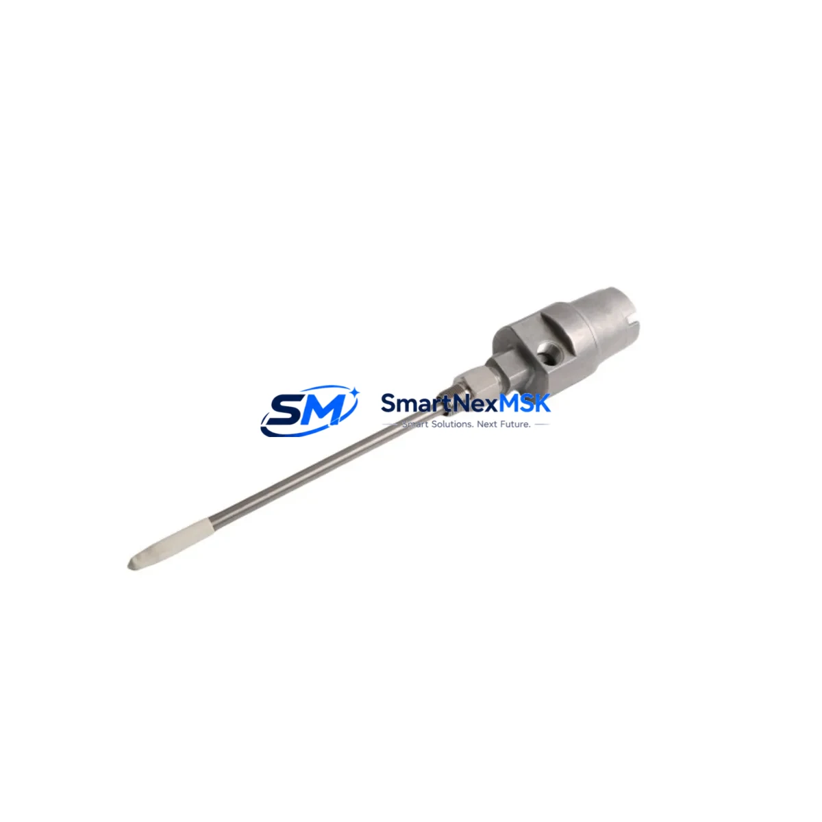
The Bently Nevada 21000-16-05-00-043-04-02 is a retrofit-ready proximity probe engineered for seamless integration into existing 3300 XL Series vibration monitoring systems. As aging machinery protection platforms reach end-of-life or face discontinued spare parts availability, this module provides a verified drop-in replacement path that preserves your existing wiring infrastructure, signal conditioning architecture, and machinery protection logic — without requiring a full system overhaul.
Industrial facilities operating rotating equipment such as turbines, compressors, pumps, and gearboxes rely on continuous shaft displacement monitoring to prevent catastrophic failure. When the original proximity probe assembly degrades or becomes unavailable through standard supply channels, the 21000-16-05-00-043-04-02 offers a technically validated alternative that maintains measurement accuracy, output signal compatibility, and system certification integrity.
This probe is designed to work within the 3300 XL transducer system ecosystem, which includes the 3300 XL 8mm Proximity Transducer System and associated extension cables and proximitor sensors. The probe tip, extension cable, and proximitor sensor must be ordered and qualified as a matched system. When replacing only the probe in an existing installation, engineers must verify that the replacement probe is compatible with the installed extension cable — such as the 330130 Series extension cable — and the corresponding proximitor, such as the 3300 XL 8mm Proximitor Sensor, to ensure the complete transducer system remains within calibrated gap voltage specifications.
Upgrade Compatibility Table
| Parameter | Details |
|---|---|
| SKU / Part Number | 21000-16-05-00-043-04-02 |
| Brand | Bently Nevada |
| Compatible Series | 3300 XL Proximity Transducer System |
| Probe Diameter | 8mm |
| Installation Type | Direct retrofit into existing probe mount; no bracket modification required |
| Signal Output | Compatible with 3300 XL Proximitor Sensor signal conditioning |
| Extension Cable Compatibility | 330130 Series extension cables (verify length and connector type on-site) |
| Communication / Interface | Analog voltage output; integrates with 3500 Series Machinery Protection System monitors |
| Replacement Recommendation | Replace as matched system (probe + extension cable + proximitor) for full calibration validity |
| Commissioning Requirement | Gap voltage verification at installation; static calibration check recommended |
| Warranty | 12 Months from date of shipment |
Retrofit Planning for Existing Automation Systems
Replacing a proximity probe in a live rotating machinery protection system requires careful pre-planning to avoid unplanned downtime and signal integrity issues. Before removing the existing 21000-series probe, maintenance engineers should document the current gap voltage reading at the proximitor output — typically between -10 VDC and -18 VDC for a properly installed 8mm system — and record the physical gap distance at the probe tip. This baseline ensures the replacement probe can be set to the same operating point during recommissioning.
The 3300 XL system architecture typically routes the probe signal through a 330130 Series extension cable to a 3300 XL 8mm Proximitor Sensor, which then feeds the conditioned voltage signal to a 3500/40M Proximitor Seismic Monitor or similar rack-mounted monitor card within the 3500 Series Machinery Protection System. When planning the retrofit, engineers should inspect the extension cable connectors for corrosion or mechanical damage, as a degraded cable can introduce signal noise that mimics probe failure. If the extension cable is also aged, replacing the full transducer set — probe, extension cable, and proximitor — is strongly recommended to restore full system accuracy.
For facilities running the 3500 Series rack, the monitor configuration stored in the 3500 System Monitor — including alert and danger setpoints, gap voltage OK limits, and transducer scale factor — should be exported via the System 1 Evolution software or Rack Configuration Software before any hardware swap. This protects the existing alarm logic and allows rapid restoration if the new probe requires setpoint adjustment. The 3500/20 Power Supply Module within the rack should also be checked to confirm it can sustain the additional current draw if multiple probes are being replaced simultaneously during a planned outage window.
In older installations where the control system integrates with a DCS or safety instrumented system via hardwired 4–20 mA or discrete relay outputs from the 3500 rack, the field wiring terminations at the I/O marshalling cabinet should be verified against the original loop drawings before the probe swap. Any changes to the proximitor output range or scale factor will propagate directly to the DCS analog input card and may require reconfiguration of the engineering unit scaling in the DCS controller. Facilities using a Bently Nevada System 1 condition monitoring platform should also update the asset configuration database to reflect the new probe serial number and calibration data after installation.
Downtime Control During System Migration
Minimizing unplanned downtime during a proximity probe replacement on a critical rotating machine requires a structured hot-swap or planned outage strategy. For machines that cannot be taken offline, some 3500 Series monitor configurations support a bypass mode that allows the monitor channel to be placed in a non-tripping state while the probe is replaced, preserving the overall machinery protection system availability. This bypass must be authorized through the site’s management of change procedure and should be time-limited to the minimum duration required for the physical swap and gap setting.
Before initiating the replacement, the engineering team should prepare a pre-tested replacement assembly — with the 21000-16-05-00-043-04-02 probe pre-connected to the matching extension cable and verified for continuity — so that the actual installation time at the machine is minimized. Having the System 1 Evolution software connected and live during the swap allows real-time monitoring of the gap voltage as the probe is threaded into the bracket, enabling precise gap setting without repeated manual measurements.
After the probe is installed and the gap voltage is confirmed within specification, the monitor channel bypass should be removed and the system allowed to stabilize for a minimum observation period before returning the machine to full load. All alarm and danger setpoints should be verified active in the 3500 Series monitor, and a test of the relay output logic — including the trip relay connected to the machine’s emergency shutdown system — should be performed if site procedures permit. Full documentation of the as-left gap voltage, probe serial number, and calibration date should be entered into the plant maintenance management system to support future predictive maintenance planning.
Retrofit Support FAQ
Q1: Is the 21000-16-05-00-043-04-02 a direct drop-in replacement for my existing 3300 XL probe?
A: In most cases, yes — provided the existing installation uses an 8mm probe mount and a compatible 330130 Series extension cable. The probe tip geometry and thread specification are consistent with the 3300 XL 8mm transducer system standard. However, the complete transducer system (probe + extension cable + proximitor) must be treated as a matched set for calibration purposes. If only the probe is being replaced, the gap voltage must be re-verified on-site after installation to confirm the system remains within the calibrated operating range.
Q2: What wiring and termination checks are required before installation?
A: Inspect the extension cable connectors at both the probe end and the proximitor end for corrosion, mechanical damage, or loose locking rings. Verify that the cable shield is properly grounded at one end only, per Bently Nevada installation guidelines, to prevent ground loop interference. At the proximitor, confirm the power supply voltage (typically -24 VDC) is within specification before connecting the new probe. At the 3500 rack, verify that the monitor channel input impedance and gap voltage OK window settings match the replacement probe’s expected output range.
Q3: How is the replacement probe tested before shipment?
A: Each 21000-16-05-00-043-04-02 unit supplied by SMARTNEXMSK undergoes functional verification prior to shipment, including output signal continuity and insulation resistance checks. Units are supplied with a 12-month warranty from the date of shipment. A test report or certificate of conformance is available upon request. Customers are advised to perform an incoming inspection and gap voltage bench test using a calibrated proximitor and target material before installation in a live system.
Q4: What if my original probe model is discontinued and I need a compatible alternative?
A: SMARTNEXMSK maintains stock of both current-production and legacy-compatible Bently Nevada proximity probe assemblies. If your original part number has been superseded or discontinued, our technical team can cross-reference the probe tip diameter, cable length, connector type, and proximitor compatibility to identify the correct replacement. Contact us with your original part number, machine type, and installed proximitor model for a compatibility assessment before ordering.
© 2026 SMARTNEXMSK. All rights reserved.
Original Source: https://smartnexmsk.com
Contact: sales@smartnexmsk.com | +86 18259474341


