Bently Nevada 21000-16-05-00-135-03-02 Spare 3300 XL: Proximity Probe Replacement for Industrial Downtime Control
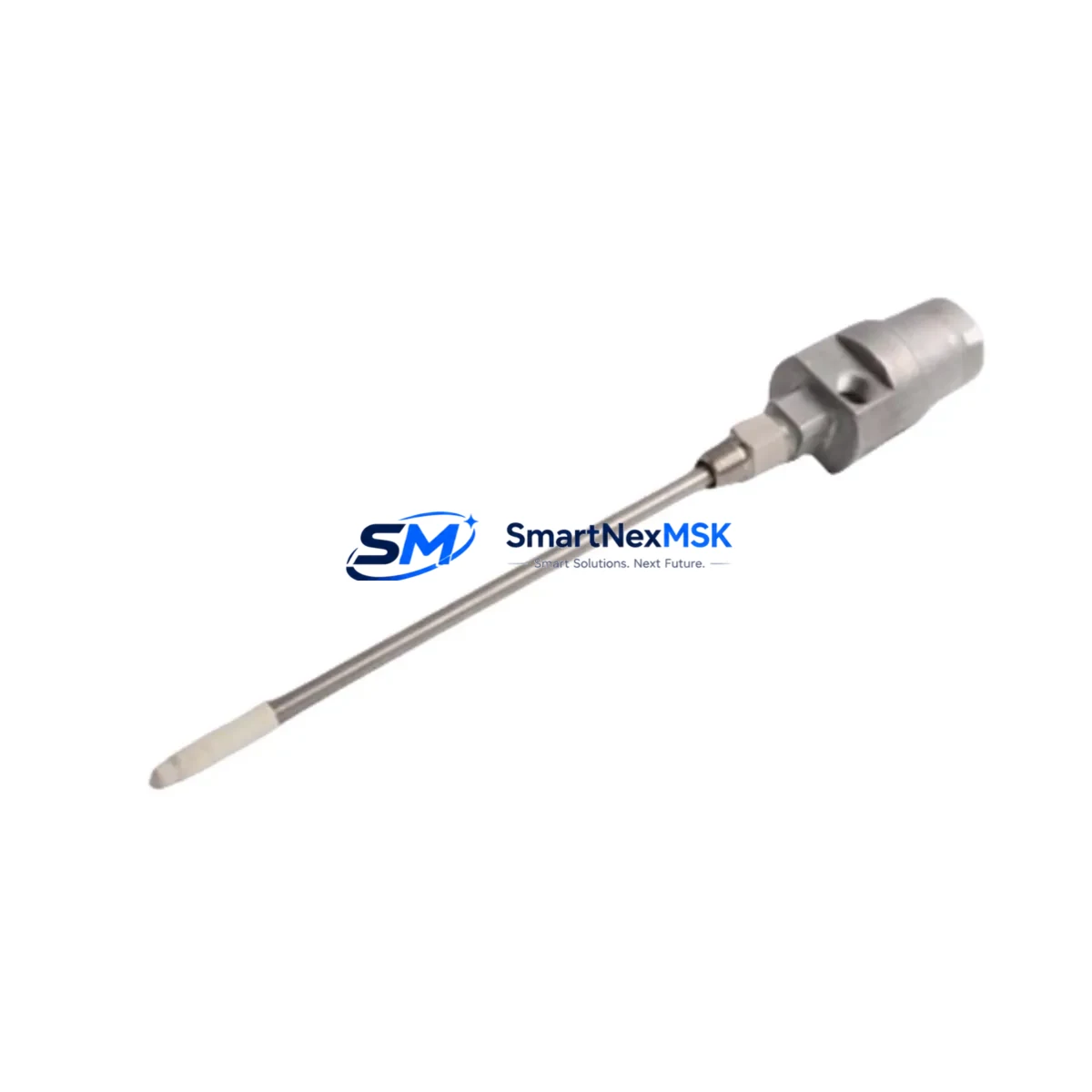
The Bently Nevada 21000-16-05-00-135-03-02 is a precision proximity probe assembly engineered for continuous vibration monitoring in rotating machinery protection systems. As a maintenance-ready spare, this unit supports rapid field replacement within Bently Nevada 3300 XL series monitor racks — minimizing unplanned downtime and restoring machine protection coverage with minimal intervention. Designed for maintenance engineers and procurement teams managing critical rotating equipment, this probe assembly is stocked, tested, and ready for immediate dispatch with a 12-month warranty.
In high-availability plants — petrochemical, power generation, compressor stations, and heavy manufacturing — the proximity probe is the first line of defense in shaft vibration and position monitoring. A failed or degraded probe can trigger false trips, mask real faults, or leave machinery unprotected. Holding a verified spare of the 21000-16-05-00-135-03-02 in your local parts inventory is a low-cost insurance policy against extended outages.
Spare Maintenance Table
| Parameter | Specification |
|---|---|
| Part Number / SKU | 21000-16-05-00-135-03-02 |
| Brand | Bently Nevada |
| Series | 3300 XL Proximity Transducer System |
| Product Type | Proximity Probe Assembly |
| Probe Diameter | 8 mm (inferred from SKU segment -16-) |
| Cable Length | 5.0 m (inferred from SKU segment -05-) |
| Output Sensitivity | 7.87 V/mm (200 mV/mil), nominal |
| Operating Frequency | DC to 10,000 Hz |
| Supply Voltage | -24 VDC (via Proximitor / extension cable) |
| Temperature Range | -35°C to +177°C (probe tip) |
| Target Material Compatibility | Steel, stainless steel, iron-based alloys |
| Connector Type | Integral coaxial, mates with 3300 XL extension cable |
| Mounting Thread | M10 x 1 (standard 3300 XL probe bracket) |
| Origin | USA |
| Compatibility | Bently Nevada 3300 XL monitor series; 3300/16 and 3300/20 monitor cards |
| Application Environment | Turbines, compressors, pumps, gearboxes, motors — API 670 installations |
| Maintenance Recommendation | Replace probe assembly when gap voltage drifts beyond ±0.5 V from baseline or physical damage is observed |
| Warranty | 12 Months |
| Condition | New / Surplus New |
| Lead Time | In stock — ships within 1–3 business days |
Maintenance Planning for Continuous Operation
When replacing the 21000-16-05-00-135-03-02 proximity probe, a thorough site inspection of the surrounding measurement chain is essential to confirm the fault is isolated to the probe and has not propagated to adjacent components. Maintenance engineers should treat a probe replacement as an opportunity for a full transducer loop audit.
Begin by inspecting the 3300 XL extension cable (typically a 5-meter or 9-meter coaxial assembly) that connects the probe to the Proximitor sensor. Extension cables are subject to mechanical fatigue at conduit entry points and connector corrosion in humid or chemically aggressive environments — a degraded cable will produce erratic gap voltage even with a new probe installed. Next, verify the 3300 XL Proximitor sensor (such as the 3300/55 or 3300/65 series) output voltage and confirm it falls within the –10 VDC to –18 VDC linear range at the nominal air gap.
At the monitor rack level, inspect the 3300/16 dual-channel vibration monitor card or 3300/20 thrust position monitor card for alarm setpoint integrity, relay output continuity, and any latched fault indicators. If the rack uses a 3300/46 keyphasor module, verify the keyphasor signal is clean and phase-referenced correctly — a degraded keyphasor can cause false 1X amplitude readings that mimic probe faults.
Check the DC power supply module feeding the monitor rack (commonly a –24 VDC regulated supply). Voltage sag or ripple on the supply rail will directly affect Proximitor output linearity and should be measured under load. Inspect terminal blocks and field wiring in the junction box for loose terminations, moisture ingress, and shield grounding continuity — ungrounded shields are a common source of electrical noise that degrades vibration signal quality.
For plants running integrated machinery protection, also review the 3500 series rack interface if the 3300 XL system feeds into a 3500/22M transient data interface or a System 1 condition monitoring platform. Signal chain integrity from probe tip to historian is critical for accurate trending and alarm management. Finally, if the installation includes temperature monitoring on the same bearing housing, verify the RTD or thermocouple transmitter is functioning — combined vibration and temperature data provides the most reliable early-warning picture for bearing health.
Site Replacement Workflow
Replacing the 21000-16-05-00-135-03-02 in the field follows a structured sequence to minimize downtime and avoid introducing new faults during the swap:
1. Pre-replacement verification: Confirm the replacement probe SKU matches the installed probe diameter, cable length, and connector configuration. The 21000-series SKU structure encodes these parameters — mismatching a probe diameter or cable length will result in incorrect sensitivity and gap voltage, requiring re-gapping and recalibration.
2. Safe isolation: De-energize the monitor channel at the rack (do not power down the entire rack if other channels are protecting live machinery). Disconnect the extension cable at the Proximitor sensor end first, then at the probe connector.
3. Probe removal and gap measurement: Remove the probe from the bracket, noting the installed gap (number of turns from flush). Record the existing gap voltage from the monitor display before disconnection as a reference baseline.
4. New probe installation: Thread the replacement 21000-16-05-00-135-03-02 into the bracket to the same approximate gap position. Reconnect the extension cable and re-energize the monitor channel. Measure the Proximitor output voltage with a calibrated DMM and adjust the probe gap until the output falls within the manufacturer’s specified linear range (typically –10 VDC to –18 VDC at the nominal gap).
5. Functional verification: Confirm the monitor card displays a valid vibration reading with no fault or not-OK indicators. Check that alarm relays are in the correct state. Log the new gap voltage and date of replacement in the equipment maintenance record.
6. Spare replenishment: After consuming a spare, initiate a replenishment order immediately to maintain minimum stock levels. For critical machinery, a minimum of one probe assembly per monitored bearing position is recommended as on-site inventory.
Spare Parts Support FAQ
Q1: Is the 21000-16-05-00-135-03-02 a direct drop-in replacement for older 3300 XL probe assemblies?
Yes — the 21000-series probe assemblies are designed for backward compatibility within the 3300 XL transducer system. Provided the probe diameter, cable length, and connector type match the installed configuration, the replacement probe will operate with existing Proximitor sensors and monitor cards without modification. Always verify the full SKU against the installed part number before ordering.
Q2: What pre-shipment testing is performed on this spare?
Each unit undergoes electrical continuity verification, coil impedance measurement, and visual inspection prior to dispatch. Units sourced as surplus new are additionally inspected for connector integrity and cable jacket condition. A test report is available upon request for critical applications.
Q3: How should this spare be stored to maintain long-term reliability?
Store the probe assembly in its original packaging or an anti-static bag in a dry, temperature-controlled environment (10°C to 40°C, <70% RH non-condensing). Avoid coiling the cable tightly or placing heavy objects on the assembly. Inspect stored spares annually for connector corrosion and cable jacket integrity. Shelf life under proper storage conditions exceeds 5 years.
Q4: What is covered under the 12-month warranty?
The 12-month warranty covers manufacturing defects, electrical failure under normal operating conditions, and connector integrity. It does not cover damage resulting from incorrect installation, over-range mechanical impact, chemical exposure beyond rated limits, or use outside the specified 3300 XL system environment. Warranty claims are processed with return of the defective unit and a completed failure description form.
© 2026 SMARTNEXMSK. All rights reserved.
Original Source: https://smartnexmsk.com
Contact: sales@smartnexmsk.com | +86 18259474341


