Bently Nevada 21000-16-10-00-098-04-02 3300 XL Retrofit: Compatible Modernization for Legacy Vibration Monitoring Systems
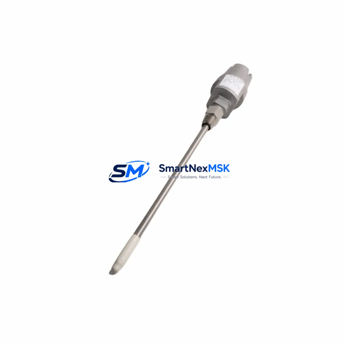
The Bently Nevada 21000-16-10-00-098-04-02 is a Proximity Probe Housing Assembly engineered for the 3300 XL Series vibration monitoring platform. As legacy installations age and original components reach end-of-life, this retrofit-ready unit provides a verified drop-in replacement path for facilities operating rotating machinery protection systems built on the Bently Nevada 3300 architecture. Whether you are managing a planned upgrade cycle, responding to an unplanned failure, or consolidating spare parts inventory, this assembly supports a smooth transition with minimal disruption to existing wiring, rack configurations, and monitoring logic.
Upgrade Compatibility Table
| Parameter | Details |
|---|---|
| SKU / Part Number | 21000-16-10-00-098-04-02 |
| Compatible Series | Bently Nevada 3300 XL Vibration Monitoring System |
| Product Type | Proximity Probe Housing Assembly |
| Mounting / Installation | Direct replacement; matches original housing dimensions and thread specification |
| Connector Interface | Compatible with standard 3300 XL extension cable and driver termination |
| Communication Compatibility | Passive analog signal path; no firmware or protocol configuration required |
| Replacement Recommendation | Suitable for direct swap of discontinued or worn OEM units in 3300 XL installations |
| Commissioning Notes | Verify gap voltage calibration (typically –10 VDC at nominal gap) after installation; confirm signal linearity with 3300 XL monitor card |
| Warranty | 12-Month Warranty — covers manufacturing defects and functional performance |
Retrofit Planning for Existing Automation Systems
Replacing the 21000-16-10-00-098-04-02 in an active plant environment requires careful coordination across several system layers. The 3300 XL platform is typically deployed in conjunction with a full rack assembly housed in a dedicated control cabinet. Before pulling the existing probe housing, engineers should document the current gap voltage reading from the associated 3300 XL monitor card — such as the 3300/16 or 3300/20 dual-channel monitor — to establish a baseline for post-installation verification.
Extension cable routing is a critical consideration. The 330130 series extension cables commonly used in 3300 XL installations have fixed lengths and must be matched to the replacement probe’s sensitivity factor. If the original cable is being reused, confirm that its connector termination is undamaged and that the cable shield is properly grounded at the driver end. The 3300 XL proximitor/driver — often a 3300/05 or 3300/55 series unit — should be inspected for output voltage stability before the new probe housing is installed, as a degraded driver can mask probe performance issues during initial commissioning.
For facilities running a broader Bently Nevada 3500 series rack alongside legacy 3300 XL equipment, it is worth confirming that the signal conditioning chain remains isolated between the two platforms. The 3500/42M position monitor and 3500/22M transient data interface modules operate on different internal architectures and should not be assumed to share calibration parameters with 3300 XL monitor cards. If the retrofit is part of a broader migration toward the 3500 platform, plan for a parallel monitoring period where both systems observe the same machine before the 3300 XL rack is decommissioned.
Control cabinet layout should also be reviewed. In installations where the 3300 XL rack shares a cabinet with a DCS I/O marshalling panel — for example, a Honeywell C300 controller node or an Emerson DeltaV M-series I/O carrier — ensure that the vibration monitor’s 4–20 mA or relay outputs are correctly mapped to the DCS analog input cards before the replacement probe is brought online. Any changes to the probe’s sensitivity or gap setting can shift the 4–20 mA output range and trigger false alarms or protective trips if the DCS scaling is not updated accordingly.
For sites using a GE Mark VIe or Rockwell Automation ControlLogix platform to aggregate machinery protection data via Modbus or Ethernet/IP, verify that the 3300 XL gateway configuration — if applicable — reflects the correct register mapping for the replacement channel. Tag names, engineering unit scaling, and alarm setpoints in the SCADA or historian layer should be reviewed and confirmed before returning the machine to service.
Downtime Control During System Migration
Minimizing unplanned downtime during a proximity probe replacement begins with pre-staging. Before the maintenance window opens, confirm that the replacement 21000-16-10-00-098-04-02 unit has been bench-tested against a known-good 3300 XL proximitor driver to verify output voltage linearity across the full measurement range. This eliminates the risk of discovering a defective replacement unit after the machine has already been taken offline.
During the swap, preserve the original PLC or DCS program logic without modification. The 3300 XL monitor card’s relay output states — typically wired to a safety PLC or a hardwired trip relay panel — should be placed in bypass mode according to the site’s management of change procedure before the probe is disconnected. This prevents a spurious trip signal from propagating to the machine’s lube oil system, turbine trip solenoid, or motor protection relay during the brief period when the probe circuit is open.
After the new probe housing is installed and the extension cable is reconnected, restore the monitor card from bypass and observe the gap voltage reading. A stable reading within the linear range of the proximitor confirms mechanical installation is correct. Run the machine at low load for a defined soak period — typically 30 to 60 minutes — while logging vibration amplitude and phase data from the 3300 XL monitor to confirm that the replacement probe is tracking shaft motion consistently with historical baseline values. Only after this verification should the bypass be fully removed and the machine returned to normal operating load.
Maintaining a documented retrofit record — including the pre- and post-installation gap voltage, the extension cable serial number, and the commissioning engineer’s sign-off — supports future maintenance planning and provides traceability for the 12-month warranty period.
Retrofit Support FAQ
Q1: Is the 21000-16-10-00-098-04-02 a direct replacement for the original Bently Nevada OEM part?
Yes. This unit is manufactured to match the original housing dimensions, thread specification, and sensitivity characteristics of the OEM 21000-16-10-00-098-04-02. It is designed for direct installation in existing 3300 XL probe mounts without mechanical modification. Gap calibration should always be verified after installation as standard commissioning practice.
Q2: What commissioning steps are required after installation?
After mechanical installation, reconnect the extension cable and restore power to the 3300 XL proximitor driver. Measure the gap voltage at the monitor card’s OK relay terminals and confirm it falls within the linear range specified for the probe sensitivity (typically –10 VDC ±1 VDC at nominal gap). Verify that the monitor card’s OK relay is energized and that no alarm or danger setpoints are exceeded at rest. Log the as-found and as-left gap voltage values in the site maintenance record.
Q3: Can this probe housing be used with both 3300 XL and 3500 series monitor cards?
The 21000-16-10-00-098-04-02 is specified for the 3300 XL platform. Compatibility with 3500 series monitor cards depends on the specific monitor module and its configured input sensitivity range. If you are migrating to a 3500/42M or similar 3500 series monitor, consult the monitor’s configuration manual to confirm that the probe sensitivity factor is supported before installation.
Q4: What does the 12-month warranty cover?
The 12-month warranty covers manufacturing defects and functional performance failures under normal operating conditions. Each unit undergoes pre-shipment functional testing prior to dispatch. Warranty claims require the original order reference and a description of the observed failure mode. Physical damage resulting from incorrect installation, over-torquing, or exposure to conditions outside the specified operating range is not covered. Contact sales@smartnexmsk.com to initiate a warranty inquiry.
© 2026 SMARTNEXMSK. All rights reserved.
Original Source: https://smartnexmsk.com
Contact: sales@smartnexmsk.com | +86 18259474341


