Bently Nevada 21000-16-10-00-103-03-02 3300 XL Spare: Precision Replacement for Vibration Monitoring Systems
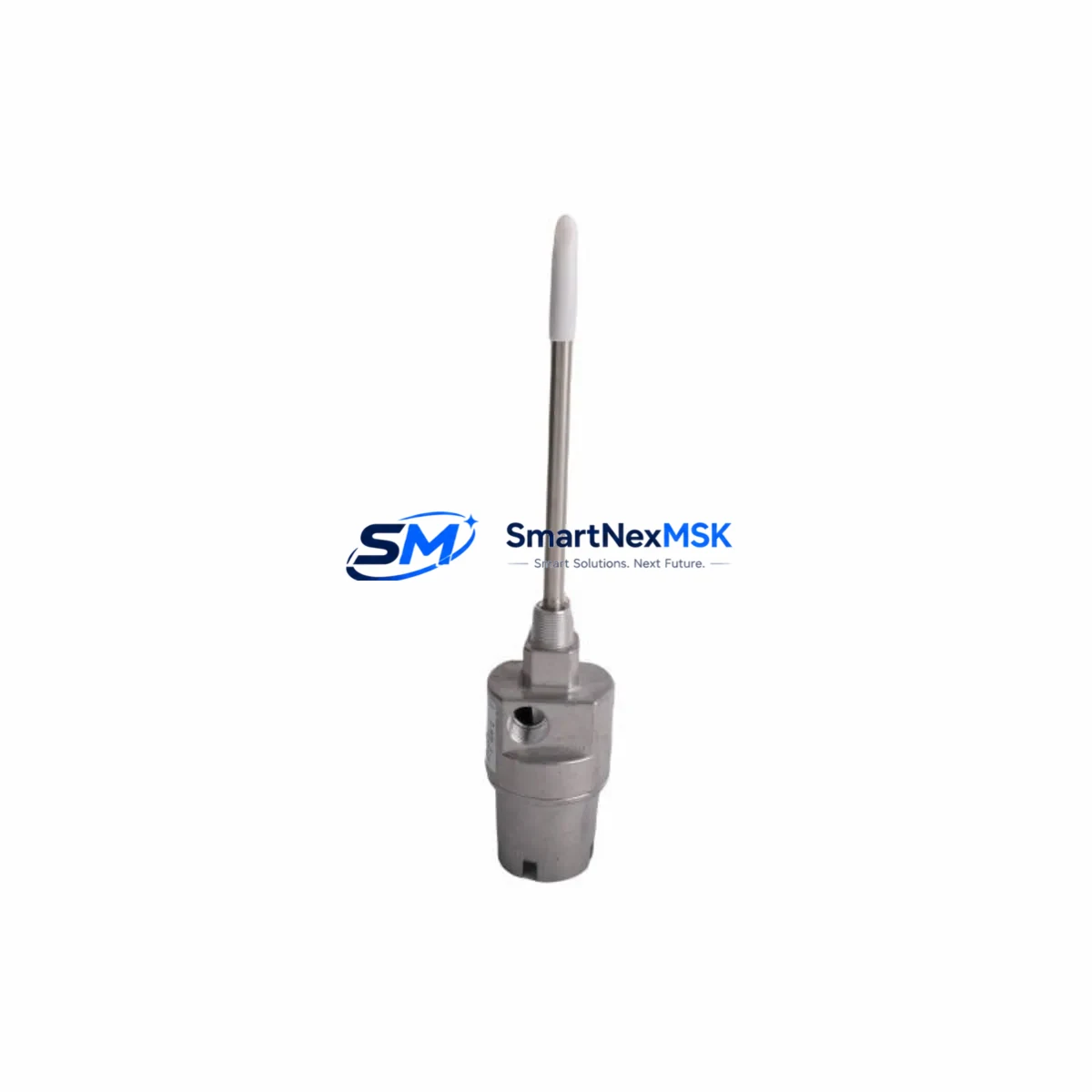
The Bently Nevada 21000-16-10-00-103-03-02 is a maintenance-critical proximity probe housing assembly designed for the 3300 XL Series continuous vibration monitoring system. This original-specification spare part is engineered to restore full measurement accuracy in rotating machinery protection applications — including turbines, compressors, pumps, and gearboxes — where unplanned downtime carries significant operational and financial risk.
For maintenance engineers managing API 670-compliant machinery protection systems, the 21000-16-10-00-103-03-02 represents a direct, drop-in replacement that eliminates the need for recalibration or system reconfiguration. Its dimensional and electrical compatibility with the 3300 XL eddy-current sensing chain ensures that gap voltage, sensitivity, and linear range specifications are preserved after installation, maintaining the integrity of your vibration alarm and trip setpoints.
Each unit is inspected and function-tested prior to dispatch. A 12-month warranty covers manufacturing defects and performance conformance, giving procurement engineers confidence in long-term spare parts planning and inventory commitments.
Spare Maintenance Table
| Parameter | Specification |
|---|---|
| Part Number | 21000-16-10-00-103-03-02 |
| Brand | Bently Nevada |
| Series | 3300 XL Proximity Transducer System |
| Component Type | Proximity Probe Housing Assembly |
| Sensing Technology | Eddy-Current (Non-contact) |
| Probe Tip Diameter | 16 mm (per SKU designation) |
| Cable Length | Per configuration suffix (03-02) |
| Output Sensitivity | 200 mV/mil (7.87 V/mm) nominal |
| Linear Range | Approx. 2–90 mil (0.05–2.29 mm) |
| Operating Temperature | -35°C to +177°C (probe body) |
| Compatibility | 3300 XL 8mm/11mm/16mm driver family; 3500 Series monitors (with adapter) |
| Standard Compliance | API 670, ISO 10816 |
| Installation Environment | Industrial — turbine halls, compressor trains, pump skids |
| Mounting | Threaded housing, locknut secured |
| Condition | New / Tested Original Spare |
| Warranty | 12 Months from date of shipment |
| Lead Time | In-stock: ships within 1–3 business days |
Maintenance Planning for Continuous Operation
When replacing the 21000-16-10-00-103-03-02 proximity probe housing during a planned outage or emergency callout, experienced maintenance engineers treat the probe replacement as a trigger for a broader inspection of the associated measurement chain and control cabinet. The 3300 XL transducer system is a series circuit: degradation in any single component propagates measurement error to the monitor and, ultimately, to the machinery protection decision logic.
Begin by inspecting the 3300 XL extension cable (typically 5 or 9 metre armoured assemblies) for jacket abrasion, connector corrosion, or shield continuity loss — these are the most common failure points in high-vibration environments. Next, verify the 3300 XL proximitor / oscillator-demodulator (such as the 330180 or 330130 series) for correct gap voltage output and supply rail stability; a faulty proximitor will produce erroneous readings even with a new probe installed.
At the monitor rack, confirm that the 3500/40M or 3500/42M proximity monitor module channel is reading within the expected gap voltage window (typically -10 VDC ± 2 V at nominal gap). If the channel has been in alarm or trip state, inspect the 3500 Rack Power Supply (e.g., 3500/15 or 3500/05) for output voltage stability under load, as power rail sag can cause false trips across multiple channels simultaneously.
For installations where the probe feeds into a Keyphasor® module (such as the 3500/25), verify that the once-per-revolution reference signal is clean and that the Keyphasor gap is within specification — this is critical for phase and 1X/2X vector accuracy in balancing and diagnostic workflows. Additionally, check the terminal strip and field wiring in the junction box for loose terminations, moisture ingress, or ground loops that could introduce noise into the measurement signal.
In older installations where the 3300 XL system interfaces with a Bently Nevada 3300/55 or 3300/65 monitor, confirm that the monitor’s internal relay outputs and OK relay contacts are functioning correctly before returning the machine to service. Faulty relay contacts in the protection chain can prevent trip signals from reaching the emergency shutdown system. Where signal conditioning is required between the proximitor output and a DCS analog input card, inspect any signal isolator or loop-powered transmitter in the circuit for correct scaling and isolation integrity.
Finally, update your spare parts register to reflect the consumed unit and reorder to maintain a minimum buffer stock — particularly for critical machines with no installed redundancy. A single spare probe assembly per critical measurement point is the industry-standard recommendation for facilities operating under API 670 machinery protection requirements.
Site Replacement Workflow
Step 1 — Isolation and permit: Obtain a work permit and confirm the machine is in a safe state. For online replacement on non-trip-critical channels, coordinate with the control room to inhibit the affected channel alarm before disconnecting the probe.
Step 2 — Record baseline readings: Note the existing gap voltage, probe serial number, and installation depth (locknut position) before removal. This data is essential for setting the replacement probe to the correct gap without a full recommissioning procedure.
Step 3 — Remove the existing probe: Loosen the locknut and unscrew the probe housing from the bracket. Disconnect the extension cable at the probe connector. Inspect the bracket bore for wear, corrosion, or thread damage.
Step 4 — Install 21000-16-10-00-103-03-02: Thread the replacement probe to the same depth as the removed unit (use the recorded locknut position as reference). Connect the extension cable and verify connector seating. Tighten the locknut to the specified torque.
Step 5 — Gap verification: Power the proximitor and measure gap voltage at the monitor or at the proximitor output terminals. Adjust probe depth until gap voltage is within the target window. Re-tighten locknut and re-verify gap voltage after tightening.
Step 6 — Functional check and channel reinstatement: Confirm the monitor channel shows OK status and that vibration readings are within expected baseline range. Remove the channel inhibit and restore normal alarm/trip logic. Document the replacement in the maintenance management system.
This workflow is compatible with both hot-standby and single-channel configurations and is applicable to legacy 3300 XL installations as well as hybrid systems where 3300 XL probes feed into 3500 Series monitors via adapter cables.
Spare Parts Support FAQ
Q1: Is the 21000-16-10-00-103-03-02 a direct replacement for older 3300 XL probe assemblies?
Yes. The 21000-16-10-00-103-03-02 is dimensionally and electrically compatible with the 3300 XL 16 mm probe family. It can replace earlier-revision housings without modification to the bracket, extension cable, or proximitor, provided the cable suffix and length match the original configuration.
Q2: What does the 12-month warranty cover?
The 12-month warranty covers manufacturing defects, dimensional non-conformance, and electrical performance outside published specifications. It runs from the date of shipment. Units that fail within the warranty period are replaced or refunded after return inspection. Warranty does not cover damage resulting from incorrect installation, mechanical impact, or operation outside rated temperature and voltage limits.
Q3: How is the unit tested before shipment?
Each 21000-16-10-00-103-03-02 unit undergoes pre-shipment inspection covering dimensional verification, connector integrity, cable continuity, and shield resistance. Functional electrical testing confirms that the probe coil impedance and resonant frequency are within the specification band for the 3300 XL driver family. A test report is available on request for critical-service applications.
Q4: Can this spare be held in long-term inventory?
Yes. The 21000-16-10-00-103-03-02 is suitable for long-term spare parts storage when kept in its original packaging in a dry, temperature-controlled environment (recommended: 10–35°C, <70% RH). There is no shelf-life limitation on the probe assembly itself. For facilities managing multi-year maintenance contracts or operating legacy 3300 XL systems where OEM supply is uncertain, maintaining a buffer stock of 1–2 units per critical machine is strongly recommended.
© 2026 SMARTNEXMSK. All rights reserved.
Original Source: https://smartnexmsk.com
Contact: sales@smartnexmsk.com | +86 18259474341


