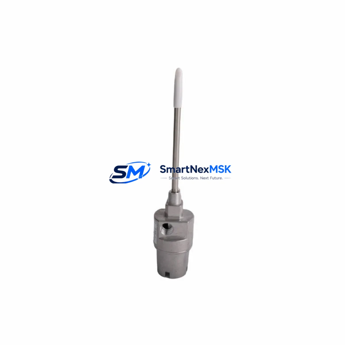
Bently Nevada 21000-16-10-00-118-03-02 Spare 3300 XL: Proximity Probe Housing for Eddy Current Vibration Monitoring
The Bently Nevada 21000-16-10-00-118-03-02 is an original proximity probe housing assembly engineered for the 3300 XL 8mm Eddy Current System — one of the most widely deployed continuous vibration monitoring platforms in rotating machinery protection. For maintenance engineers managing turbines, compressors, pumps, and gearboxes, this component sits at the heart of shaft displacement measurement and early fault detection. A failed or degraded probe housing directly compromises the integrity of your vibration signal chain, creating unplanned downtime risk and potential machinery damage.
Sourcing an original, tested replacement for the 21000-16-10-00-118-03-02 is a critical step in any planned or emergency maintenance event. This unit ships fully tested against Bently Nevada factory specifications, with a 12-month warranty covering manufacturing defects. Fast dispatch is available to support urgent shutdown recovery scenarios.
Spare Maintenance Table
| Parameter | Specification |
|---|---|
| Part Number | 21000-16-10-00-118-03-02 |
| Brand | Bently Nevada |
| Series | 3300 XL 8mm Eddy Current System |
| Product Type | Proximity Probe Housing Assembly |
| Probe Diameter | 8mm |
| System Compatibility | 3300 XL Series, 3300/16 Monitor, 3300/20 Monitor |
| Signal Type | Eddy Current (non-contact displacement) |
| Typical Application | Shaft radial/axial vibration, thrust position monitoring |
| Installation Environment | Industrial — turbine halls, compressor skids, pump stations |
| Condition | Original, factory-spec tested |
| Warranty | 12 Months |
| Origin | United States |
| Weight | 1080 g |
Maintenance Planning for Continuous Operation
When replacing the 21000-16-10-00-118-03-02 probe housing during a scheduled outage or emergency repair, experienced maintenance engineers treat this as an opportunity to audit the entire vibration signal chain. The probe housing is mechanically and electrically coupled to the 3300 XL extension cable (typically 5m or 9m armored type) — cable condition, connector seating, and shield continuity should be verified before reinstalling a new housing. The 3300 XL proximitor/oscillator (driver module) is the next critical component: check its output voltage at the monitor input and confirm it falls within the –18 VDC to –24 VDC nominal range for an 8mm probe system.
At the rack level, inspect the 3300/16 or 3300/20 vibration monitor card for alarm relay status, OK relay dropout, and any latched fault indicators. If the monitor card has been in service for more than five years without calibration, this is an appropriate time to schedule a bench calibration or swap in a spare card from your critical spares inventory. The 3300 XL power supply module feeding the monitor rack should also be load-tested — a sagging supply rail is a common root cause of intermittent OK relay trips that are misdiagnosed as probe failures.
For plants running integrated machinery protection systems, the signal from this probe chain typically feeds into a System 1 Evolution or legacy System 1 condition monitoring platform. Verify that the channel configuration in the software matches the new probe’s gap voltage and sensitivity settings after replacement. If your facility uses a Keyphasor module (e.g., 3300/55 or 3500/25) for phase reference, confirm that the Keyphasor signal is stable and that the once-per-revolution marker is correctly detected post-replacement.
In control cabinet inspections, also check the terminal strip and field wiring connecting the proximitor to the monitor card — corroded terminals or loose ferrules can introduce noise that mimics probe degradation. Where signal isolation is required between the vibration monitor and the DCS or safety system, inspect any signal isolator or barrier modules (such as MTL or P+F Zener barriers) in the loop. Finally, review the fuse or circuit breaker protecting the monitor rack power feed, and confirm that the rack’s backplane connectors are fully seated and free of oxidation.
Site Replacement Workflow
Replacing the 21000-16-10-00-118-03-02 in the field follows a structured sequence to minimize downtime and avoid secondary faults. Begin by placing the associated monitor channel in bypass mode (or coordinating with the control room to inhibit the trip function) before disconnecting the probe. Remove the old housing carefully — note the gap distance setting if the probe tip-to-target gap was previously optimized for your specific shaft material and surface finish. Install the new housing, set the gap to the manufacturer-recommended starting point (typically 1.0–1.5mm for 8mm probes), and verify the proximitor output voltage is within specification before re-enabling the monitor channel.
This replacement procedure is compatible with all 3300 XL series monitors and does not require firmware changes or system reconfiguration, making it a direct drop-in for aging or failed housings. For plants transitioning from older 3300 non-XL probe assemblies, confirm connector and thread compatibility before installation. Documenting the as-found and as-left gap voltage readings in your CMMS supports future trend analysis and reduces diagnostic time in subsequent outages.
Spare Parts Support FAQ
Q: Is the 21000-16-10-00-118-03-02 compatible with both 3300/16 and 3300/20 monitor cards?
A: Yes. The 21000-16-10-00-118-03-02 housing is designed for the 3300 XL 8mm Eddy Current System and is compatible with the full range of 3300 XL series monitor cards, including the 3300/16 and 3300/20, provided the extension cable and proximitor are also 8mm XL series components.
Q: What testing is performed before shipment?
A: Each unit undergoes electrical continuity verification, output voltage check at nominal gap, and physical inspection for thread integrity and connector condition. A test report is available upon request for critical plant applications.
Q: How should I manage long-term spare parts inventory for 3300 XL probe systems?
A: Industry best practice for rotating machinery protection systems is to maintain a minimum of one spare probe housing, one spare extension cable, and one spare proximitor per critical machine train. For plants with multiple identical trains, a pooled critical spares strategy reduces carrying cost while maintaining rapid response capability.
Q: What is the warranty coverage and what does it include?
A: All units carry a 12-month warranty from the date of shipment, covering manufacturing defects and electrical performance to specification. Warranty claims are supported with replacement or credit. Units damaged by incorrect installation, overvoltage, or mechanical impact are not covered under warranty terms.
© 2026 SMARTNEXMSK. All rights reserved.
Original Source: https://smartnexmsk.com
Contact: sales@smartnexmsk.com | +86 18259474341


