Bently Nevada 21000-28-05-00-75-01-02: Retrofit-Ready Proximity Probe for 3300 XL Control Systems
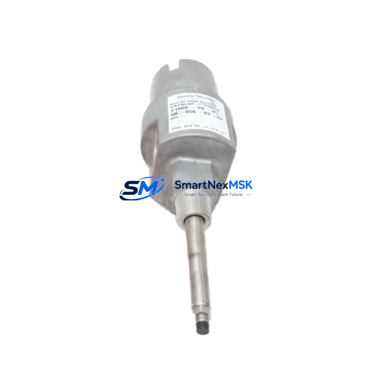
The Bently Nevada 21000-28-05-00-75-01-02 is a high-precision eddy-current proximity probe engineered for the 3300 XL Proximity Transducer System — one of the most widely deployed vibration and position monitoring platforms in rotating machinery protection. As legacy installations age and OEM support windows close, this probe serves as a verified drop-in replacement for discontinued or end-of-life units, enabling plant engineers to restore full system functionality without redesigning the monitoring architecture or replacing the entire transducer chain.
Designed to interface directly with the Bently Nevada 3300 XL extension cable and 3300 XL proximitor/oscillator driver, the 21000-28-05-00-75-01-02 maintains the original signal conditioning path. The probe tip diameter, thread specification, and cable termination are dimensionally compatible with existing probe holders and armored conduit runs, minimizing mechanical rework during installation. Engineers replacing worn or damaged probes on turbine shafts, compressor journals, or pump bearing housings will find that the mounting geometry and gap voltage calibration requirements align precisely with the original Bently Nevada documentation.
When integrating this probe into an existing 3300 XL system, the first verification step is confirming that the proximitor driver — typically a 3300 XL 8mm or 5mm proximitor — is matched to the correct probe series. The 21000-28-05-00-75-01-02 is a 5mm series probe, and pairing it with an incompatible proximitor will produce erroneous gap voltage readings and may trigger false shutdown signals on the connected Bently Nevada 3500 rack or 3300 monitoring system. Before energizing the replacement probe, technicians should verify the DC gap voltage falls within the linear range specified in the system calibration record, typically between −10 VDC and −18 VDC depending on the target material and gap distance.
Upgrade Compatibility Table
| Parameter | Specification / Recommendation |
|---|---|
| SKU / Part Number | 21000-28-05-00-75-01-02 |
| Series Compatibility | Bently Nevada 3300 XL Proximity Transducer System |
| Probe Type | Eddy-Current Proximity Probe, 5mm Series |
| Mating Proximitor | 3300 XL 5mm Proximitor/Oscillator Driver |
| Extension Cable Compatibility | 3300 XL Extension Cable (standard armored, 5m / 9m) |
| Monitoring Rack Compatibility | Bently Nevada 3500 Series, 3300 Series Monitoring Systems |
| Installation Interface | Drop-in replacement; existing probe holder and conduit compatible |
| Gap Voltage Range | −10 VDC to −18 VDC (verify against site calibration record) |
| Communication / Signal | Analog voltage output; no protocol migration required |
| Retrofit Complexity | Low — mechanical and electrical drop-in; gap recalibration required |
| Commissioning Requirement | Gap voltage verification, sensitivity check, alarm setpoint confirmation |
| Warranty | 12-Month Warranty from date of shipment |
Retrofit Planning for Existing Automation Systems
A successful retrofit of the 21000-28-05-00-75-01-02 begins well before the maintenance window opens. Plant engineers should pull the existing loop drawing to confirm the cable routing from the probe tip through the 3300 XL extension cable to the proximitor junction box. In many installations, the extension cable is routed through conduit shared with other instrumentation, and the cable connector type — typically a MIL-C-5015 style bayonet connector — must be inspected for corrosion or mechanical damage before reuse.
The proximitor driver mounted in the field junction box or control cabinet should be checked for firmware revision compatibility if the site has previously upgraded from a standard 3300 proximitor to a 3300 XL proximitor. In systems where the monitoring rack has been upgraded to a Bently Nevada 3500/42M or 3500/40M vibration monitor module, the input channel configuration in the rack’s software — typically managed through System 1 Evolution or the legacy System 1 software — must reflect the correct transducer type and sensitivity factor (typically 7.87 V/mm or 200 mV/mil for 5mm probes).
For plants running mixed-generation equipment, it is common to find the 3300 XL proximity system operating alongside older Bently Nevada 7200 series probes on adjacent machinery trains. When planning a phased retrofit, engineers should document which machinery trains are still running 7200 series transducers and which have already been migrated to the 3300 XL platform, as the two systems use different proximitor power supply requirements and different gap voltage calibration curves. The 3300 XL power supply module in the control cabinet — often a dedicated 24 VDC rail — must be verified for adequate current capacity before adding replacement probes to the loop.
In control cabinets where space is constrained, the replacement probe cable routing may require the use of a 3300 XL armored extension cable in a non-standard length. Field technicians should confirm the total cable length — probe cable plus extension cable — does not exceed the system’s specified maximum loop resistance, as excessive resistance will shift the gap voltage calibration and may cause the 3500 rack to report a transducer not OK (TNOK) fault. If the existing DCS or safety instrumented system (SIS) receives a 4–20 mA retransmission signal from the 3500 rack, the output scaling should be reverified after probe replacement to ensure the process variable displayed on the operator HMI screen remains accurate.
Additional components commonly involved in a 3300 XL probe retrofit include the 3300 XL proximitor power supply, the 3500/01 rack power supply module, the 3500/20 keyphasor module (where shaft speed reference is required), the 3500/42M proximitor I/O module, and the System 1 Evolution software license for configuration changes. In some installations, the Bently Nevada TK-3 programming cable or the 3500 rack communication gateway is required to push updated channel configuration to the rack without taking the entire monitoring system offline.
Downtime Control During System Migration
Minimizing unplanned downtime during a proximity probe replacement requires a structured pre-outage preparation protocol. Before the maintenance window, the replacement 21000-28-05-00-75-01-02 probe should be bench-tested using a portable proximitor test kit to confirm the probe’s sensitivity and linearity are within specification. This pre-shipment functional test — which SMARTNEXMSK performs on all outgoing units — reduces the risk of discovering a defective replacement probe after the machine has already been taken offline.
During the outage, the original probe should be removed carefully to preserve the probe holder threads and the armored cable jacket. The gap should be set using a non-ferrous feeler gauge or a calibrated gap-setting tool, targeting the nominal gap specified in the original installation record. Once the probe is installed and the gap is set, the proximitor output voltage should be measured at the junction box terminal strip before reconnecting the extension cable to the monitoring rack, isolating the probe-to-proximitor loop from the rack to prevent nuisance alarms during the gap-setting procedure.
After the loop is reconnected and the 3500 rack is returned to normal monitoring mode, the channel should be observed through at least one full machine startup cycle to confirm that the vibration and position readings are stable and consistent with the pre-outage baseline. If the site uses a Bently Nevada System 1 historian, the post-replacement data should be compared against the pre-outage trend to verify that no step change in the DC gap voltage or dynamic vibration amplitude has occurred. Any deviation greater than 10% from the baseline should be investigated before returning the machine to full load.
For critical machinery where continuous monitoring is required, a temporary bypass or voting logic arrangement in the SIS may be necessary during the probe replacement window. Plant safety engineers should review the SIS bypass procedure and ensure that the bypass is logged, time-limited, and approved in accordance with the site’s management of change (MOC) process before the maintenance window begins.
Retrofit Support FAQ
Q1: Is the 21000-28-05-00-75-01-02 a direct replacement for the discontinued Bently Nevada 21000 series probes?
Yes. The 21000-28-05-00-75-01-02 is designed as a functional and dimensional replacement for discontinued 21000 series proximity probes used in 3300 XL transducer systems. The probe tip geometry, thread specification, and cable termination are compatible with existing probe holders and extension cables. A gap voltage verification and sensitivity check are required after installation to confirm calibration.
Q2: What wiring changes are required when replacing the probe in an existing 3300 XL installation?
In most cases, no wiring changes are required. The replacement probe connects to the existing 3300 XL extension cable using the standard bayonet-style connector. If the existing extension cable shows signs of insulation damage or connector corrosion, the cable should be replaced simultaneously to avoid intermittent signal faults. Terminal connections at the proximitor junction box should be inspected and retorqued to the specified torque value during the replacement procedure.
Q3: How do I verify compatibility with my Bently Nevada 3500 monitoring rack before installation?
Confirm that the 3500 rack channel is configured for a 5mm proximity probe with a sensitivity of 7.87 V/mm (200 mV/mil). Check the 3500/42M or 3500/40M module configuration in System 1 or the rack’s front-panel display to verify the transducer type selection. If the rack was previously configured for an 8mm probe, the sensitivity factor and alarm setpoints must be updated before the replacement probe is energized to avoid false alarms or missed fault detection.
Q4: What does the 12-month warranty cover, and what is the shipping lead time?
All units supplied by SMARTNEXMSK carry a 12-month warranty from the date of shipment, covering manufacturing defects and functional failures under normal operating conditions. Warranty claims are supported by our technical team with replacement or repair at no additional cost. Standard in-stock units ship within 3–5 business days. For urgent requirements, expedited shipping is available — contact sales@smartnexmsk.com or call +86 18259474341 to confirm current stock availability and lead time.
© 2026 SMARTNEXMSK. All rights reserved.
Original Source: https://smartnexmsk.com
Contact: sales@smartnexmsk.com | +86 18259474341


