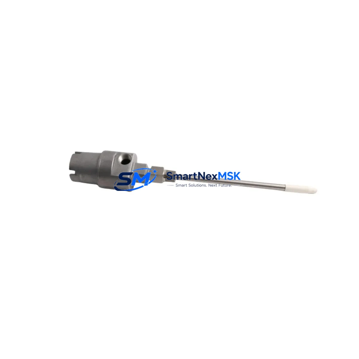
Bently Nevada 21000-28-05-15-028-04-02 3300 XL Spare: Precision Proximity Probe for Industrial Downtime Control
The Bently Nevada 21000-28-05-15-028-04-02 is an original proximity probe housing assembly engineered for the 3300 XL Series continuous vibration monitoring system. In rotating machinery protection environments — turbines, compressors, pumps, and gearboxes — this probe is a critical front-line sensor. When it fails or degrades, the entire vibration monitoring loop is compromised, exposing rotating assets to undetected shaft displacement, bearing wear, and catastrophic mechanical failure. Maintaining a verified spare of the 21000-28-05-15-028-04-02 in your parts inventory is not optional — it is a fundamental requirement of any serious predictive maintenance program.
This unit ships fully tested against Bently Nevada factory specifications, with dimensional verification of the probe tip, cable integrity check, and output sensitivity confirmation. Each unit is backed by a 12-month warranty covering manufacturing defects and performance deviation. Fast dispatch from stocked inventory ensures your maintenance team can restore monitoring continuity within the shortest possible window.
Spare Maintenance Table
| Parameter | Specification |
|---|---|
| SKU / Part Number | 21000-28-05-15-028-04-02 |
| Brand | Bently Nevada |
| Series | 3300 XL Proximity Transducer System |
| Product Type | Proximity Probe Housing Assembly |
| Probe Tip Diameter | 8 mm (standard 3300 XL configuration) |
| Cable Length | As per original assembly specification |
| Output Sensitivity | 200 mV/mil (7.87 V/mm) nominal |
| Operating Temperature | -35°C to +177°C |
| Gap Voltage Range | -2 VDC to -18 VDC |
| Target Material Compatibility | AISI 4140 steel, standard rotating shaft materials |
| Connector Type | 3300 XL system-compatible coaxial |
| Mounting Thread | Standard 3300 XL bracket/holder compatible |
| Application Environment | Turbines, compressors, pumps, gearboxes, motors |
| Compliance | API 670 compatible monitoring loop |
| Origin | USA |
| Warranty | 12 Months — manufacturing defects and performance |
| Pre-shipment Testing | Output sensitivity, gap voltage, cable continuity |
Maintenance Planning for Continuous Operation
When a maintenance or reliability engineer schedules replacement of the 21000-28-05-15-028-04-02, the scope of inspection should extend well beyond the probe itself. The 3300 XL proximity transducer system is a complete measurement chain, and degradation in any component will corrupt vibration data or trigger nuisance trips.
Begin with the 3300 XL Extension Cable (typically 5-metre or 9-metre assemblies). Extension cables are subject to jacket cracking, connector corrosion, and shield continuity loss — particularly in high-temperature or chemically aggressive environments. A probe replacement that retains a degraded extension cable will not restore system accuracy. Inspect and replace as a matched set where possible.
Next, verify the 3300 XL Proximitor Sensor (driver/oscillator module), such as the 330180 or 330130 series. The Proximitor converts the probe’s raw eddy-current signal into a calibrated voltage output. If the Proximitor has accumulated operating hours comparable to the failed probe, proactive replacement during the same maintenance window eliminates a second planned outage.
Inspect the 3300 XL Monitor Module installed in the rack — typically a dual-channel or quad-channel vibration monitor card. Confirm that channel input impedance, alarm setpoints, and OK relay logic are functioning correctly after probe replacement. A faulty monitor card can mask a correctly functioning new probe.
Check the terminal block and field wiring at the junction box. Loose terminations, corroded lugs, or undersized conductors introduce resistance that shifts gap voltage readings. Torque all terminals to specification and verify wire labelling matches the as-built drawing.
Review the power supply module feeding the 3300 XL rack — commonly a 3300/20 or equivalent redundant DC supply. Voltage ripple or dropout events can cause false OK-relay trips and should be measured under load before returning the system to service.
For systems with Keyphasor probes (e.g., 330980 series) installed on the same shaft, confirm Keyphasor gap voltage and signal quality simultaneously. Phase reference accuracy directly affects 1X and 2X vibration vector calculations used in balancing and diagnostic trending.
Where the control cabinet also houses temperature monitoring modules (RTD or thermocouple input cards), verify that thermowell connections and transmitter zero/span calibration remain within tolerance. Vibration and temperature data are often reviewed together during root-cause analysis of bearing events.
If the machine train includes a 3500 Series rack for overspeed or thrust monitoring alongside the 3300 XL vibration system, confirm that the inter-system communication and relay voting logic is intact. A probe replacement that inadvertently disrupts a relay output can affect trip authority across both systems.
Finally, update the CMMS work order with the replacement probe serial number, gap voltage as-found and as-left readings, and the next scheduled inspection interval. This documentation supports warranty claims, audit readiness, and long-term reliability trending.
Site Replacement Workflow
Step 1 — Permit and Isolation: Obtain a valid work permit. Confirm the machine is in a safe state for maintenance access. Do not de-energize the 3300 XL rack until the permit authorises it — some facilities require the monitoring system to remain live until the machine is confirmed at rest.
Step 2 — As-Found Documentation: Record the existing probe gap voltage (typically displayed on the monitor front panel or via the DCS/historian). Photograph the probe mounting orientation, cable routing, and connector labelling before disassembly.
Step 3 — Probe Removal: Loosen the probe locknut and back the probe out of the holder. Disconnect the extension cable at the field junction box. Inspect the probe tip for mechanical damage, contamination, or corrosion that may indicate a root cause beyond normal wear.
Step 4 — New Probe Installation: Thread the 21000-28-05-15-028-04-02 replacement into the holder. Set the initial gap to the manufacturer-specified starting distance (typically 1.0–1.5 mm for 8 mm probes). Connect the extension cable and verify connector seating.
Step 5 — Gap Voltage Verification: Energise the Proximitor and measure gap voltage at the monitor input. Adjust probe depth until gap voltage falls within the linear range centre (typically -10 VDC ±1 VDC for standard 3300 XL configurations). Tighten the locknut to the specified torque.
Step 6 — System Functional Check: Confirm the monitor channel shows OK status. Verify alarm and danger setpoints are active. Perform a slow-roll check if the machine can be safely rotated to confirm 1X signal quality before returning to full speed.
Step 7 — As-Left Documentation: Record final gap voltage, probe serial number, and installation date. Update the CMMS and spare parts inventory. Return the replaced probe to the supplier or dispose of per site procedures.
This workflow minimises downtime, ensures system compatibility, and maintains the integrity of the API 670 monitoring loop without requiring specialist commissioning support.
Spare Parts Support FAQ
Q1: Is the 21000-28-05-15-028-04-02 a direct replacement for the original Bently Nevada part?
Yes. This unit is an original Bently Nevada 21000-28-05-15-028-04-02 proximity probe housing assembly, manufactured to the same dimensional and electrical specification as the part it replaces. No recalibration of the Proximitor or monitor is required when replacing like-for-like within the 3300 XL system.
Q2: What pre-shipment testing is performed before dispatch?
Each unit undergoes output sensitivity verification, gap voltage linearity check, cable shield continuity measurement, and connector integrity inspection. Test results are available upon request. Units that do not meet factory specification are not dispatched.
Q3: How should this spare be stored if not immediately installed?
Store in the original packaging in a dry, temperature-controlled environment (10°C–35°C, <70% RH non-condensing). Avoid proximity to strong magnetic fields or solvents. Inspect the probe tip and connector before installation if the unit has been in storage for more than 12 months.
Q4: What does the 12-month warranty cover?
The warranty covers manufacturing defects, output sensitivity deviation beyond ±5% of nominal, and mechanical failure under normal operating conditions. It does not cover damage resulting from incorrect installation, overvoltage, mechanical impact, or operation outside the specified temperature range. Warranty claims are processed within 5 business days of receipt of the returned unit.
© 2026 SMARTNEXMSK. All rights reserved.
Original Source: https://smartnexmsk.com
Contact: sales@smartnexmsk.com | +86 18259474341


