Bently Nevada 21000-28-10-00-167-04-02 3300 XL Spare: Spare Replacement & Industrial Downtime Risk Control
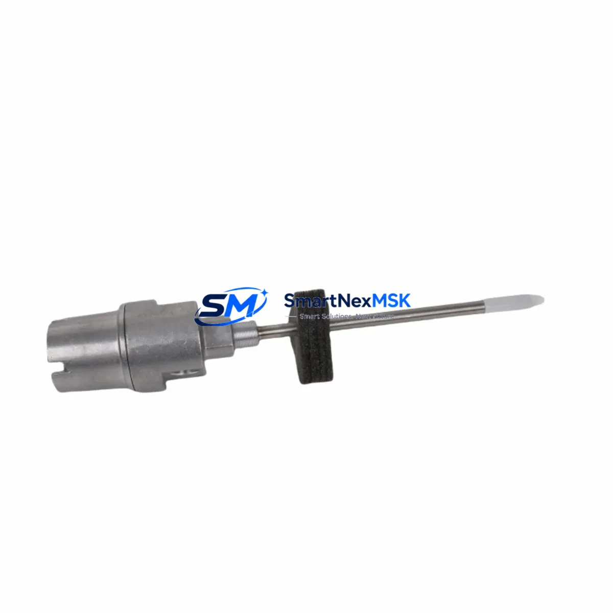
The Bently Nevada 21000-28-10-00-167-04-02 is an original proximity probe assembly engineered for the 3300 XL continuous vibration monitoring system. In rotating machinery protection environments — turbines, compressors, pumps, and gearboxes — this probe is a critical front-line sensor. When it fails or degrades, the entire vibration channel goes blind, exposing the machine to undetected shaft displacement, rub events, and catastrophic bearing failure. Maintaining a verified spare on the shelf is not optional; it is a fundamental element of any serious predictive maintenance program.
This unit ships as an original Bently Nevada component, fully tested prior to dispatch, and is backed by a 12-month warranty covering manufacturing defects and functional performance. Each unit is inspected for tip condition, cable integrity, connector seating, and sensitivity calibration before packaging. Orders are processed with same-day or next-business-day dispatch to minimize your exposure window during unplanned outages.
Spare Maintenance Table
| Parameter | Specification / Detail |
|---|---|
| Part Number | 21000-28-10-00-167-04-02 |
| Brand | Bently Nevada |
| Series | 3300 XL Proximity Transducer System |
| Component Type | Proximity Probe Assembly |
| Probe Tip Diameter | 8 mm (standard 3300 XL series) |
| Cable Length | 167 cm (as indicated in SKU suffix) |
| Connector Type | Coaxial, compatible with 3300 XL extension cables and proximitors |
| Gap Voltage Range | –10 VDC to –18 VDC (nominal –12 VDC at 1.0 mm gap) |
| Sensitivity | 7.87 V/mm (200 mV/mil) |
| Operating Temperature | –35°C to +177°C |
| Target Material Compatibility | Steel, 4140 alloy, Inconel (per Bently Nevada target guidelines) |
| System Compatibility | 3300 XL Proximitor, 3300 XL 8mm Proximity System |
| Installation Environment | Industrial: turbine bearing housings, compressor pedestals, pump bearing caps |
| Warranty | 12 Months — covers manufacturing defects and functional performance |
| Pre-shipment Testing | Yes — tip condition, cable continuity, connector integrity, sensitivity check |
| Origin | USA |
Maintenance Planning for Continuous Operation
When a maintenance or reliability engineer schedules replacement of the 21000-28-10-00-167-04-02 probe, the work scope should never be limited to the probe alone. The 3300 XL proximity transducer system is a three-component chain — probe, extension cable, and proximitor — and degradation in any one element corrupts the entire channel output. During the same maintenance window, inspect and if necessary replace the 330130 extension cable connecting the probe to the proximitor, and verify the 330180 proximitor module for correct gap voltage output and driver current draw.
At the rack level, confirm that the 3300/16-02-01-00 I/O module is receiving clean channel signals and that the 3300/20-01-00 power supply module is delivering stable ±24 VDC to the proximitor loop. A marginal power supply is a common root cause of intermittent proximity channel faults that are misdiagnosed as probe failures. While the cabinet is open, check the 3300/46M monitor module for any latched alerts or bypass conditions that may have masked earlier degradation.
For facilities running parallel vibration and axial position monitoring, the 330103 radial vibration monitor and 330106 thrust position monitor should be included in the same inspection cycle. Wiring terminations at the 3300 XL terminal board should be torqued to specification and inspected for corrosion, particularly in humid or offshore environments. If the machine train also uses a 3500/42M proximitor I/O module in a 3500 series rack for redundant monitoring, verify that the channel configuration and gap setpoints remain synchronized with the 3300 XL channel.
Procurement engineers building a minimum viable spare parts kit for a 3300 XL-protected machine train should stock at minimum: one probe assembly (21000-28-10-00-167-04-02), one matched extension cable, one proximitor, and one spare power supply module. This four-item kit covers the most common field-replaceable failure modes and enables a trained technician to restore full vibration monitoring within a single shift.
Site Replacement Workflow
Step 1 — Isolation and documentation: Before removing the probe, record the existing gap voltage from the proximitor output (typically displayed on the 3300 XL monitor or DCS historian). This baseline confirms the target surface condition and provides a reference for post-installation verification.
Step 2 — Mechanical removal: Loosen the probe locknut and back the probe out of the bracket. Inspect the probe tip for impact damage, pitting, or contamination. Inspect the bracket threads and confirm the replacement probe thread pitch matches (M10×1 for standard 8 mm 3300 XL probes).
Step 3 — Installation and gapping: Thread the 21000-28-10-00-167-04-02 replacement probe into the bracket. Using a calibrated gap tool or digital voltmeter on the proximitor output, set the probe-to-target gap to achieve the nominal –12 VDC output (approximately 1.0 mm gap on steel targets). Tighten the locknut to the specified torque.
Step 4 — System verification: With the machine at rest, confirm the gap voltage is stable and within the monitor’s OK band. Check the 3300 XL monitor for any channel fault or not-OK indication. If the machine can be safely rotated on turning gear, observe the dynamic signal for noise or dropout before returning to normal operation.
Step 5 — Documentation and spare replenishment: Log the replacement in the maintenance management system (CMMS) with the new probe serial number, installation date, and gap voltage. Immediately initiate a purchase order to replenish the consumed spare, maintaining the minimum stock level defined in your spare parts strategy.
This workflow is compatible with legacy 3300 series installations and supports migration from older 3300/05 or 3300/10 probe assemblies where the bracket geometry and thread specification are unchanged. No firmware or configuration changes are required in the 3300 XL monitor when replacing a like-for-like probe assembly.
Spare Parts Support FAQ
Q1: Is the 21000-28-10-00-167-04-02 a direct replacement for older 3300 series probe assemblies with the same tip diameter and cable length?
A: In most cases, yes. The 3300 XL probe series maintains backward mechanical compatibility with earlier 3300 bracket designs sharing the M10×1 thread and 8 mm tip diameter. However, always verify the proximitor model and confirm the sensitivity specification (7.87 V/mm) matches the monitor channel configuration before installation.
Q2: What pre-shipment testing is performed on each unit?
A: Every unit undergoes tip condition inspection, full cable continuity check, connector seating verification, and sensitivity confirmation against Bently Nevada factory specifications before dispatch. A test record is available upon request for quality-critical applications.
Q3: How should this spare be stored to preserve its service life?
A: Store in the original packaging or an ESD-safe, moisture-controlled environment between –20°C and +70°C. Avoid coiling the cable tighter than the minimum bend radius (typically 50 mm for 3300 XL cables). Inspect stored spares annually for connector corrosion and cable jacket integrity.
Q4: What is covered under the 12-month warranty?
A: The warranty covers manufacturing defects, connector failures, cable open-circuit faults, and sensitivity out-of-specification conditions arising from production. Physical damage from improper installation, over-torquing, or impact is excluded. Warranty claims are processed with return authorization; replacement units are dispatched within 5 business days of claim approval.
© 2026 SMARTNEXMSK. All rights reserved.
Original Source: https://smartnexmsk.com
Contact: sales@smartnexmsk.com | +86 18259474341


