Bently Nevada 21000-33-05-00-035-03-02 Spare 3300 XL: Precision Spare Parts for Industrial Downtime Control
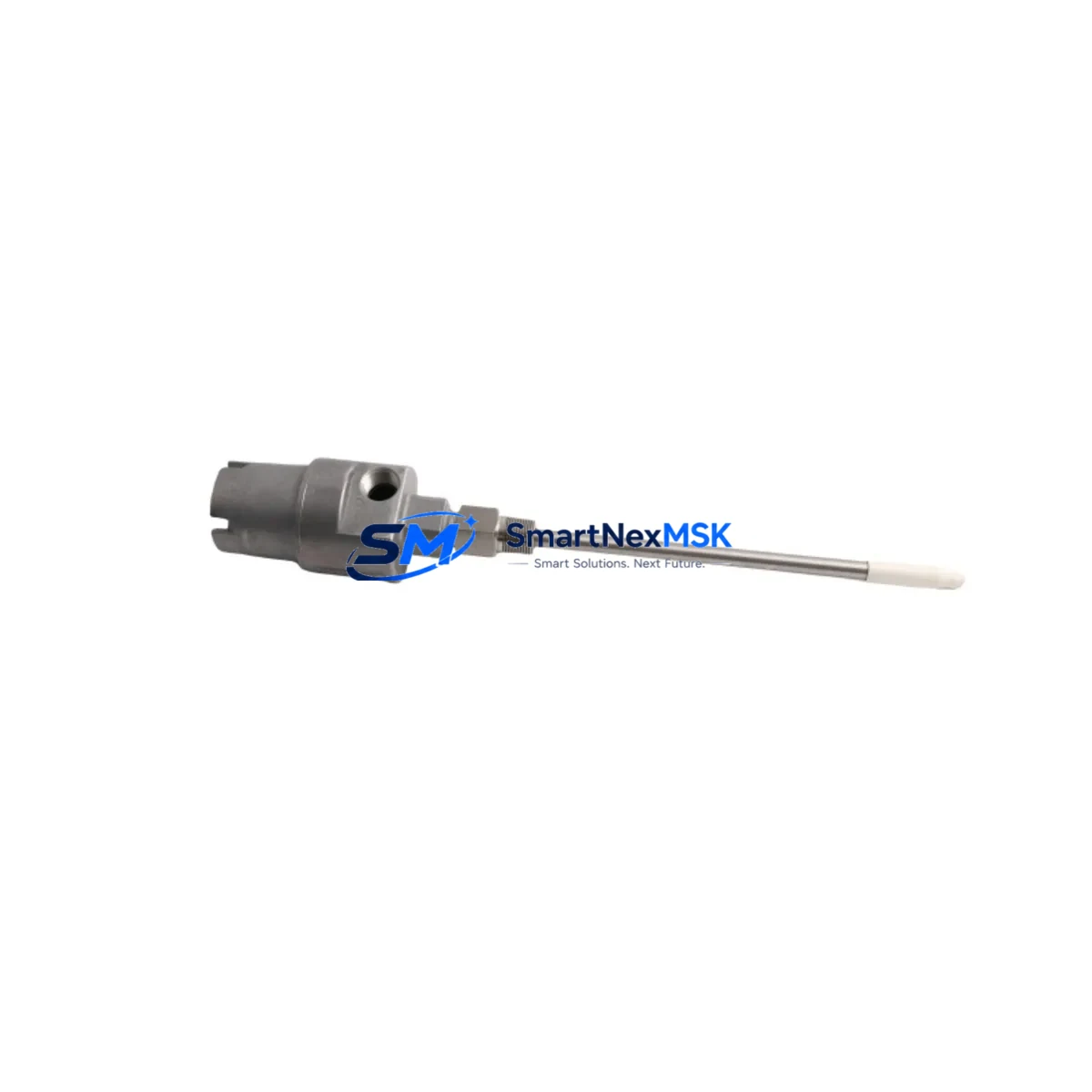
The Bently Nevada 21000-33-05-00-035-03-02 is an original proximity probe housing engineered for the 3300 XL Transducer System — one of the most widely deployed vibration monitoring platforms in rotating machinery protection. Whether you are managing a planned turnaround, responding to an unplanned trip, or building a critical-spares inventory for a gas turbine, compressor train, or steam turbine control cabinet, this component delivers the dimensional accuracy, material integrity, and signal-path reliability that maintenance engineers depend on.
Sourced directly from authorized supply channels, every unit undergoes pre-shipment functional verification. Each order ships with a 12-month warranty covering manufacturing defects and performance conformance to original Bently Nevada specifications.
Spare Maintenance Table
| Parameter | Specification |
|---|---|
| Part Number / SKU | 21000-33-05-00-035-03-02 |
| Brand | Bently Nevada |
| Series | 3300 XL Transducer System |
| Product Type | Proximity Probe Housing |
| Probe Cable Length | 5.0 m (standard extension cable configuration) |
| Thread / Mounting | M10 × 1.0 standard probe thread |
| Gap Voltage Range | −10 VDC to −18 VDC (nominal −12 VDC at 1.0 mm gap) |
| Output Sensitivity | 7.87 V/mm (200 mV/mil) |
| Operating Temperature | −35 °C to +121 °C |
| Target Material Compatibility | AISI 4140 / 4340 steel, Inconel 718 |
| IP Rating | IP67 (sealed housing) |
| Origin | USA |
| Warranty | 12 Months — manufacturing defects & performance conformance |
| Shipping | Tested & inspected before dispatch; DHL / FedEx express available |
| Compatibility | 3300 XL 8 mm, 3300 XL 11 mm Proximitor® Sensor systems |
| Maintenance Recommendation | Replace probe housing when gap voltage drift exceeds ±0.5 VDC or physical damage is observed on tip or cable jacket |
Maintenance Planning for Continuous Operation
When a proximity probe housing such as the 21000-33-05-00-035-03-02 is flagged for replacement during a routine vibration survey or after a machinery trip, experienced maintenance engineers know that the probe itself is rarely the only component requiring attention. A thorough inspection of the entire measurement loop is essential to restore full system integrity and prevent repeat failures.
Begin with the Bently Nevada 3300 XL Proximitor® Sensor (e.g., 330180-91-05 or 330180-51-00 series) mounted in the same cabinet slot. Proximitor sensors accumulate thermal stress and connector wear over years of continuous service; replacing the probe housing without verifying the sensor’s output linearity and power draw is a common source of post-maintenance nuisance trips. Inspect the extension cable assembly — typically a 5-metre or 9-metre armored cable — for jacket cracking, connector corrosion, and continuity. A degraded extension cable will introduce gap voltage noise that mimics shaft runout.
At the terminal cabinet level, check the 3300/16 or 3300/20 rack power supply module for output voltage stability under load. An aging power supply delivering marginal −24 VDC can cause multiple channel alarms simultaneously, masking the true fault source. Inspect the I/O terminal blocks (Bently Nevada 3300/10 or equivalent) for loose terminations and oxidized contacts — a common finding in high-humidity or coastal plant environments.
If the machinery protection system interfaces with a DCS or safety PLC via 4–20 mA or relay outputs, verify that the signal isolator or barrier module in the loop is within calibration. Galvanic isolation barriers from brands such as MTL or P+F are frequently overlooked during probe-focused maintenance windows. Similarly, confirm that any relay output modules driving shutdown logic have not developed contact resistance that could delay trip response.
For systems using Bently Nevada System 1 software for condition monitoring, cross-check the channel configuration after hardware replacement to ensure gap, direct, and 1X/2X vector parameters are correctly mapped. Communication modules connecting the rack to the historian — whether via Modbus RTU, Ethernet/IP, or OPC-DA — should be power-cycled and link-tested after any rack disturbance. Finally, review the fuse ratings on the probe power circuit; an undersized fuse that has been operating near its thermal limit may have degraded and should be replaced as a low-cost preventive measure alongside the probe housing.
Stocking a matched set of the probe housing, extension cable, and Proximitor sensor as a critical spare kit reduces mean time to repair (MTTR) from hours to minutes during an unplanned outage — a strategy strongly recommended for any rotating equipment classified as production-critical.
Site Replacement Workflow
Step 1 — Isolation & Permit: Obtain a hot-work or cold-work permit as applicable. De-energize the Proximitor sensor channel at the rack terminal strip, not at the field junction box, to avoid disturbing adjacent channels.
Step 2 — Gap Measurement Before Removal: Record the existing gap voltage using a calibrated DVM before disconnecting the probe. This baseline confirms whether the housing or the Proximitor sensor was the primary fault source and provides a reference for the reinstallation gap setting.
Step 3 — Remove Old Housing: Use the correct probe spanner to avoid damaging the mounting boss threads. Inspect the boss bore for corrosion, thread damage, or debris before installing the replacement 21000-33-05-00-035-03-02 unit.
Step 4 — Install & Set Gap: Thread the new housing to finger-tight, then adjust to achieve the target gap voltage (typically −10.0 VDC ± 0.2 VDC for most 3300 XL applications). Lock with the jam nut to the torque specified in the Bently Nevada installation drawing.
Step 5 — Re-energize & Verify: Restore power to the channel and confirm gap voltage, direct amplitude, and 1X vector readings are within normal operating bands in System 1 or the local rack display. Clear any latched alarms only after verification.
Step 6 — Documentation: Update the maintenance management system (CMMS) with the replaced part number, installation date, gap voltage as-left value, and technician sign-off. This record supports future predictive maintenance scheduling and warranty claims.
This workflow is compatible with direct replacement of legacy Bently Nevada 7200 series probe housings in retrofitted brackets, provided the thread pitch and tip diameter are confirmed to match the target material clearance requirements.
Spare Parts Support FAQ
Q1: What is the shelf life and storage recommendation for the 21000-33-05-00-035-03-02 before installation?
When stored in the original sealed packaging at 15–25 °C with relative humidity below 60%, the probe housing maintains full specification compliance for a minimum of 5 years. Avoid storage near strong magnetic fields or solvents. Inspect the cable jacket and connector pins for any signs of degradation before installation if the unit has been in storage for more than 2 years.
Q2: How do I verify compatibility with my existing 3300 XL Proximitor Sensor before ordering?
Confirm the Proximitor sensor model number on the rack module label. The 21000-33-05-00-035-03-02 is designed for use with 3300 XL 8 mm and 11 mm Proximitor sensors operating on standard −24 VDC rack power. If your system uses an older 7200 series Proximitor, consult the Bently Nevada cross-reference guide or contact our technical team with your rack model number for a compatibility confirmation before ordering.
Q3: What pre-shipment testing is performed on each unit?
Every 21000-33-05-00-035-03-02 unit is bench-tested for gap voltage linearity across the full measurement range, cable continuity, connector integrity, and housing dimensional conformance prior to dispatch. A test report is available upon request. Units are shipped in anti-static, moisture-barrier packaging with a serialized inspection label.
Q4: What does the 12-month warranty cover, and how is a warranty claim processed?
The 12-month warranty covers manufacturing defects, premature electrical failure under normal operating conditions, and non-conformance to published Bently Nevada specifications. It does not cover damage resulting from incorrect installation, overvoltage, mechanical impact, or use outside the rated environmental envelope. To initiate a warranty claim, contact sales@smartnexmsk.com with the order number, installation date, site conditions, and a description of the observed failure. Replacement units are dispatched within 5 business days of claim approval.
© 2026 SMARTNEXMSK. All rights reserved.
Original Source: https://smartnexmsk.com
Contact: sales@smartnexmsk.com | +86 18259474341


