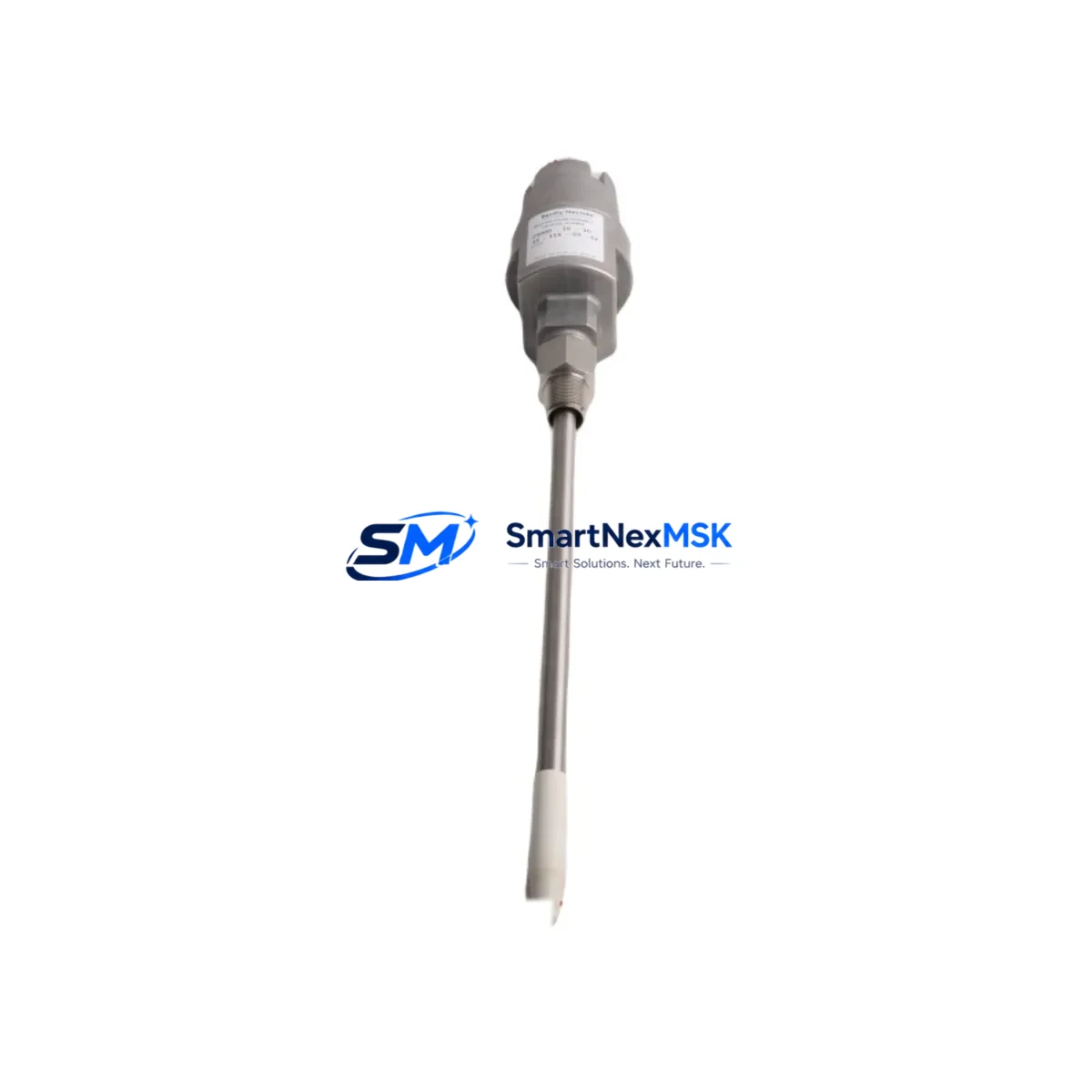
Bently Nevada 21000-34-10-00-085-04-02 Spare 21000 Series: Precision Replacement for Vibration Monitoring Continuity
Unplanned downtime in rotating machinery monitoring is one of the most costly events in industrial operations. The Bently Nevada 21000-34-10-00-085-04-02 proximity probe housing assembly is a critical component within the 21000 Series eddy-current proximity measurement system — a platform widely deployed in turbines, compressors, pumps, and generators across oil & gas, power generation, petrochemical, and heavy manufacturing facilities. When this component fails or degrades, the entire vibration and position monitoring loop is compromised, leaving rotating assets unprotected and maintenance teams blind to developing faults.
Sourced as an original-specification spare, this unit is designed to deliver direct, drop-in compatibility with existing 21000 Series installations. Every unit undergoes pre-shipment functional verification to confirm dimensional accuracy, electrical continuity, and housing integrity before dispatch. A 12-month warranty is included as standard, supporting both planned maintenance schedules and emergency replacement scenarios.
Spare Maintenance Table
| Parameter | Specification / Detail |
|---|---|
| Part Number / SKU | 21000-34-10-00-085-04-02 |
| Brand | Bently Nevada |
| Series | 21000 Series Proximity Measurement System |
| Product Type | Proximity Probe Housing Assembly |
| Probe Gap Range | Typically 0.25 mm – 2.25 mm (per 21000 Series standard) |
| Output Signal | DC voltage proportional to gap distance (eddy-current principle) |
| Compatible Driver / Oscillator | Bently Nevada 21000 Series proximitor / oscillator-demodulator |
| Thread / Mounting | Per OEM specification for 21000-34 sub-series |
| Cable Length | 085 (8.5 m extension cable configuration) |
| Temperature Range | -35°C to +177°C (probe tip, standard) |
| Application Environment | Rotating machinery: turbines, compressors, pumps, motors |
| Measurement Type | Radial vibration, axial position, differential expansion |
| Origin | USA (Bently Nevada / Baker Hughes) |
| Condition | Original spare, pre-shipment tested |
| Warranty | 12 months from date of shipment |
| Lead Time | In-stock: ships within 3–5 business days |
Maintenance Planning for Continuous Operation
For maintenance engineers managing a 21000 Series vibration monitoring loop, replacing the 21000-34-10-00-085-04-02 probe housing in isolation is rarely sufficient for a complete, reliable restoration. A structured inspection of the full measurement chain is essential to prevent repeat failures and ensure the monitoring system returns to full accuracy.
Begin with the extension cable — the 085-series cable pairing this probe must be inspected for jacket damage, connector corrosion, and continuity. A degraded extension cable is a frequent source of signal noise that mimics probe failure. Next, verify the Bently Nevada 21000 Series proximitor (oscillator-demodulator) module: check the output voltage at the calibrated gap, confirm the power supply rail (typically –24 VDC), and inspect the terminal block connections for oxidation or loose terminations.
At the control cabinet level, inspect the barrier isolator or Zener barrier associated with this channel — particularly in hazardous-area installations where intrinsic safety barriers protect the field loop. Confirm the signal conditioning module or rack card in the monitoring system (such as a 3500 Series rack if the 21000 probe feeds into a Bently Nevada 3500 system) is receiving a clean DC signal within the expected voltage window. Check the rack power supply module for output stability; a marginal power supply can cause intermittent probe faults that are difficult to diagnose without isolating the supply.
For the I/O side, verify that the 4–20 mA output card or relay output module associated with the vibration channel is functioning correctly and that alarm setpoints have not drifted. If the system uses a communication gateway or Modbus/PROFIBUS interface module to relay vibration data to a DCS or SCADA platform, confirm that the channel mapping is intact after the probe replacement. In older installations, also inspect the terminal strip and marshalling panel wiring for insulation breakdown, particularly in high-temperature or high-humidity environments.
Finally, for facilities managing long-term asset life extension on aging 21000 Series installations, maintaining a minimum spare inventory of the probe housing, extension cable, and proximitor module ensures that any single-point failure can be resolved within one shift — eliminating the multi-day lead times that turn a minor fault into a major production loss event.
Site Replacement Workflow
Step 1 — Isolation & Lockout: Follow site LOTO procedures. Isolate the proximitor power supply (–24 VDC) before disconnecting the probe. Document the existing gap voltage reading from the monitoring system prior to shutdown.
Step 2 — Probe Removal: Carefully unthread the 21000-34-10-00-085-04-02 housing from the probe holder bracket. Inspect the bracket for wear, corrosion, or thread damage. Replace the bracket if thread integrity is compromised — a loose probe mount introduces mechanical noise that cannot be corrected by calibration.
Step 3 — Extension Cable Inspection: Disconnect the extension cable at both the probe and proximitor ends. Perform a continuity and insulation resistance check. If resistance is outside specification, replace the extension cable as part of this maintenance event rather than deferring it.
Step 4 — New Probe Installation: Install the replacement 21000-34-10-00-085-04-02 housing. Set the initial gap per the OEM calibration chart for the target shaft material. Reconnect the extension cable with clean, torqued connectors.
Step 5 — Calibration & Verification: Restore power to the proximitor. Measure the output voltage at the set gap and confirm it falls within the linear range specified for the 21000 Series. Compare against the pre-shutdown baseline. Adjust gap as needed to achieve the target output voltage.
Step 6 — System Restoration: Confirm alarm and trip setpoints are active in the monitoring rack. Verify the channel is communicating correctly to the DCS or SCADA system. Log the replacement in the maintenance management system (CMMS) with the new probe serial number and calibration data.
This workflow minimizes total downtime to a single planned window and ensures the replacement is fully validated before the asset returns to service — reducing the risk of a repeat trip event caused by an incomplete installation.
Spare Parts Support FAQ
Q1: Is the 21000-34-10-00-085-04-02 a direct replacement for the original Bently Nevada part?
Yes. This unit is sourced to original Bently Nevada specifications for the 21000 Series proximity measurement system. It is dimensionally and electrically compatible with existing probe holders, extension cables, and proximitor modules in the 21000 Series platform. No modification to the existing installation is required for a standard replacement.
Q2: What pre-shipment testing is performed on this spare?
Each unit undergoes dimensional inspection, housing integrity verification, and electrical continuity testing prior to dispatch. Units that do not meet specification are quarantined and not shipped. A test record is available upon request for quality-critical applications.
Q3: How should this spare be stored if not immediately installed?
Store in the original packaging in a dry, temperature-controlled environment (10°C – 40°C, <70% RH, non-condensing). Avoid storage near strong magnetic fields or sources of mechanical vibration. Inspect the connector and probe tip for contamination before installation if the unit has been in storage for more than 12 months.
Q4: What is covered under the 12-month warranty?
The 12-month warranty covers manufacturing defects and functional failures under normal operating conditions consistent with the 21000 Series application environment. It does not cover damage resulting from incorrect installation, overvoltage, mechanical impact, or use outside the specified temperature and environmental ratings. Warranty claims are supported with a replacement unit or full refund at the buyer’s discretion.
© 2026 SMARTNEXMSK. All rights reserved.
Original Source: https://smartnexmsk.com
Contact: sales@smartnexmsk.com | +86 18259474341


