Bently Nevada 21505-00-12-10-02 Retrofit-Ready Proximity Probe for 3300 XL Control Systems
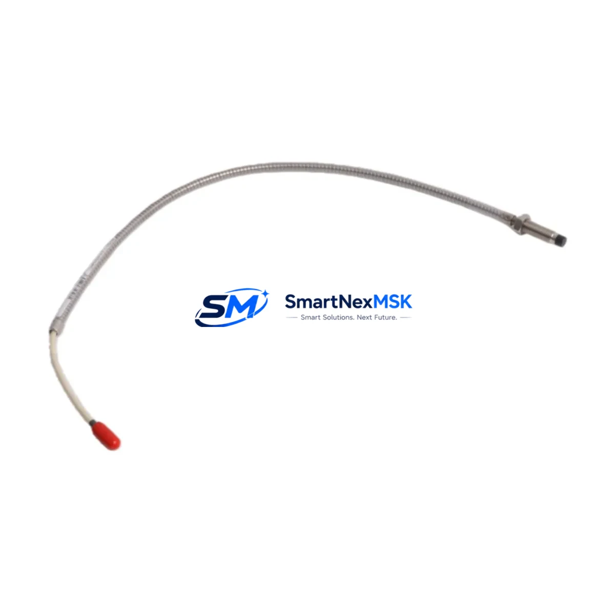
The Bently Nevada 21505-00-12-10-02 is an 8mm eddy-current proximity transducer engineered for the 3300 XL Series vibration monitoring platform. As legacy 3300 XL installations approach end-of-service milestones, this probe serves as the primary retrofit and drop-in replacement solution for facilities operating rotating machinery — including steam turbines, gas compressors, centrifugal pumps, and gearboxes — where continuous shaft vibration and position monitoring is mission-critical.
Whether you are replacing a failed probe on an emergency basis, executing a planned outage upgrade, or migrating from an older 3300 Series (non-XL) architecture to the current 3300 XL platform, the 21505-00-12-10-02 is designed to minimize engineering rework. Its standardized 8mm sensing tip, 5-metre integral cable, and -24 VDC bias voltage output are fully compatible with the 3300 XL 8mm Proximitor® Sensor (such as the 330180 series) and the associated 3500/42M or 3500/40M proximity monitor cards installed in the 3500 Series rack.
Upgrade Compatibility Table
| Parameter | 21505-00-12-10-02 (This Unit) | Legacy 3300 (Non-XL) Probe | Retrofit Notes |
|---|---|---|---|
| Probe Tip Diameter | 8 mm | 8 mm | No mechanical modification required |
| Cable Length | 5 m (standard) | 5 m / 9 m variants | Verify extension cable length; use 330130 extension if needed |
| Output Bias Voltage | -24 VDC nominal | -24 VDC nominal | Compatible with 3300 XL Proximitor® and 3500/42M monitor |
| Sensitivity | 7.87 V/mm (200 mV/mil) | 7.87 V/mm | No rescaling required in 3500 rack configuration |
| Linear Range | 0.25 – 2.26 mm (10 – 89 mil) | 0.25 – 2.26 mm | Gap setting unchanged; re-verify air gap at installation |
| Connector Type | Integral coaxial, TNC-compatible | Integral coaxial | Mates directly with 330130 extension cable |
| Monitor Compatibility | 3500/42M, 3500/40M, 3300 XL | 3300 (non-XL) monitor | Confirm monitor firmware supports XL probe calibration table |
| Installation Standard | API 670 compliant | API 670 compliant | No change to machinery protection standard |
| Warranty | 12 Months from shipment date | Covered under SMARTNEXMSK standard warranty policy | |
Retrofit Planning for Existing Automation Systems
A successful retrofit of the 21505-00-12-10-02 into an operating plant begins well before the maintenance window opens. Engineers should first audit the existing 3300 XL Proximitor® Sensor (typically a 330180-91-05 or equivalent) to confirm it remains serviceable, since the probe and Proximitor form a calibrated pair. If the Proximitor is also degraded, both components should be replaced simultaneously to avoid a second outage.
Next, inspect the 330130 extension cable running from the probe to the Proximitor. Damaged shielding or corroded TNC connectors are a common source of signal noise that is often misattributed to the probe itself. Replacing the extension cable during the same outage eliminates this variable. From the Proximitor, the signal travels to the 3500/42M Proximitor®/Velomitor® Monitor or the 3500/40M Proximitor® Monitor housed in the 3500 Series Rack. Verify that the rack’s power supply — typically a 3500/15 Power Supply — is delivering stable ±24 VDC before energizing the new probe.
Terminal wiring at the monitor I/O module should be documented with photographs before disconnection. The 3500/42M uses a standard barrier terminal block; confirm that wire ferrules are in good condition and that shield grounding follows the plant’s single-point grounding scheme. Incorrect shield termination is the leading cause of elevated noise floors after probe replacement.
Once the probe is physically installed and the air gap is set to the manufacturer’s recommended value (typically 1.0 – 1.5 mm for most shaft materials), power up the Proximitor and confirm the bias voltage output falls within the -10 to -18 VDC operating window at the monitor input. The 3500/42M will display a Not OK status if the gap is outside the linear range, which simplifies field verification. Before returning the machine to service, run a full channel functional test using the Bently Nevada System 1 software or the rack’s front-panel test points to validate alarm and danger setpoints against the original configuration baseline.
For facilities migrating from a standalone 3300 Series rack to a fully integrated 3500 Series architecture, the probe replacement is often the simplest part of the project. The more complex tasks involve re-mapping I/O channels in the 3500/20 Rack Interface Module, updating the System 1 database with new channel tags, and coordinating with the DCS or safety system team to re-establish the 4–20 mA or relay outputs that feed the plant’s DeltaV or Ovation control system. Scheduling these steps in parallel with the physical installation is the most effective way to compress total outage duration.
Downtime Control During System Migration
Minimizing unplanned downtime during a proximity probe replacement requires a structured pre-outage checklist and a clearly defined go/no-go decision point. Before the maintenance window, confirm that the replacement 21505-00-12-10-02 probe has been bench-tested against a known-good Proximitor to verify sensitivity and bias voltage. This pre-shipment functional test — performed at our facility in Xiamen before dispatch — is included with every unit and documented on the accompanying test report.
During the outage, preserve the original program logic in the 3500 Series rack by exporting the full rack configuration from Rack Configuration Software (RCS) before any hardware changes. This backup ensures that if a monitor card is inadvertently reset during the swap, the configuration can be restored in minutes rather than hours. Similarly, capture a screenshot or export of the System 1 trend data for the affected channel so that post-restart vibration levels can be compared directly against the pre-outage baseline — a requirement for most machinery protection audit trails.
If the machine cannot be fully shut down, consider a hot-swap approach where the new probe is pre-gapped and connected to a spare channel on the 3500/42M monitor while the original channel remains active. Once the new channel is verified healthy, the machine can be briefly unloaded (rather than fully stopped) while the primary channel is switched over. This technique is particularly effective on parallel-train compressor installations where one train can carry load during the swap.
After restart, monitor the first 30 minutes of operation closely. A sudden increase in 1× or 2× vibration amplitude relative to the pre-outage baseline typically indicates an air gap error or a grounding issue rather than a mechanical problem. Correcting these in the first hour of operation avoids a second shutdown and keeps total maintenance time within the planned window.
Retrofit Support FAQ
Q1: Is the 21505-00-12-10-02 a direct drop-in replacement for the original Bently Nevada probe in my 3300 XL system?
Yes. The 21505-00-12-10-02 maintains the same 8mm tip diameter, 5-metre cable length, -24 VDC bias output, and 200 mV/mil sensitivity as the original factory specification. No recalibration of the 3300 XL Proximitor® or the 3500 monitor card is required, provided the air gap is correctly set during installation.
Q2: What wiring changes are needed when replacing the probe?
No wiring changes are required at the monitor terminal block. The probe connects to the existing 330130 extension cable using the standard TNC coaxial interface. Inspect the extension cable connector and shield continuity before reuse. If the extension cable shows signs of damage or corrosion, replace it simultaneously to avoid signal integrity issues.
Q3: How do I verify compatibility with my 3500/42M monitor before installation?
Open the Rack Configuration Software (RCS) and confirm that the channel is configured for an 8mm, 200 mV/mil, -24 VDC probe type. If the channel was previously configured for a non-XL 3300 Series probe with a different calibration table, update the probe type selection to match the 21505-00-12-10-02 specification. Save and download the updated configuration to the rack before installing the new probe.
Q4: What does the 12-month warranty cover, and what is the shipping lead time?
Every 21505-00-12-10-02 unit ships with a 12-month warranty covering manufacturing defects and functional failures under normal operating conditions. Each unit undergoes a pre-shipment functional test — bias voltage, sensitivity, and cable continuity — before dispatch from our Xiamen warehouse. Standard lead time is 3–7 business days for in-stock units. Express air freight is available for emergency replacement requirements. Contact sales@smartnexmsk.com or call +86 18259474341 for stock confirmation and expedited shipping options.
© 2026 SMARTNEXMSK. All rights reserved.
Original Source: https://smartnexmsk.com
Contact: sales@smartnexmsk.com | +86 18259474341


