Bently Nevada 22810-00-14-10-02 Retrofit-Ready Proximity Probe for 3300 XL Control Systems
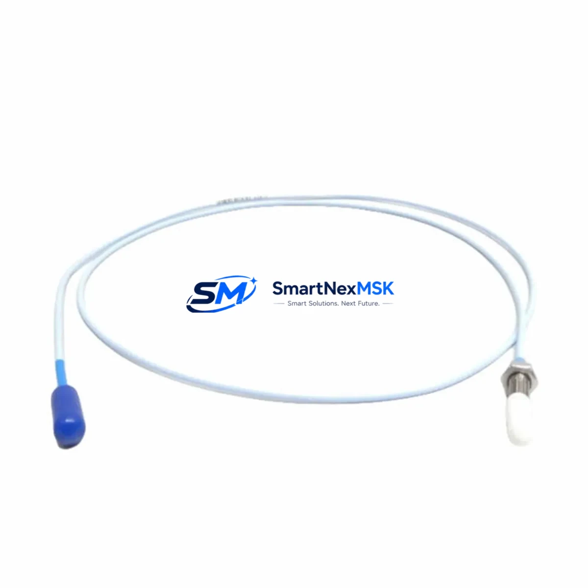
The Bently Nevada 22810-00-14-10-02 is an eddy-current proximity probe engineered for seamless integration into Bently Nevada 3300 XL vibration monitoring systems. As legacy machinery monitoring infrastructure ages across power generation, petrochemical, and rotating equipment facilities, the demand for verified drop-in replacements that preserve existing wiring, calibration, and system architecture has never been greater. This probe is designed to meet that demand — delivering full compatibility with the 3300 XL signal conditioning chain without requiring reprogramming, recalibration of the proximitor, or modification of existing terminal wiring.
Whether you are replacing a failed probe on a critical turbine train, upgrading a worn sensor on a compressor skid, or executing a planned maintenance overhaul on a multi-shaft rotating machine, the 22810-00-14-10-02 provides the dimensional accuracy, gap voltage linearity, and cable assembly specifications required by the 3300 XL architecture. The probe is compatible with the Bently Nevada 3300 XL 8mm Proximitor® module and operates within the standard -24 VDC bias voltage range expected by the signal conditioning electronics.
When planning a retrofit using this probe, engineers should verify the following before installation: the existing proximitor module type (confirm it is a 3300 XL 8mm series, such as the 3300 XL 8mm Proximitor® 330180 or 330181), the extension cable length and connector type (the 22810 series uses a standard coaxial assembly — confirm total system cable length does not exceed the calibrated range), the terminal block wiring at the I/O module or junction box, and the gap voltage setpoint stored in the System 1 or rack-mounted monitor. If the plant is running a 3500 Series rack alongside legacy 3300 XL hardware, note that the 3500/42M Proximitor I/O Module uses a different connector and signal path — cross-compatibility must be verified before substitution.
For facilities migrating from older 3300 RAM or 3300/16 monitors to the current 3300 XL platform, the 22810-00-14-10-02 supports the transition by maintaining the same probe body diameter, thread specification, and armored cable assembly as the predecessor models. This allows maintenance teams to reuse existing probe holders, conduit runs, and terminal strip assignments, significantly reducing retrofit labor and downtime exposure.
Upgrade Compatibility Table
| Parameter | Specification / Recommendation |
|---|---|
| Compatible Monitor Series | Bently Nevada 3300 XL (primary); verify before use with 3500 Series |
| Probe Type | Eddy-Current (Non-Contact) Proximity Probe, 8mm |
| Proximitor Compatibility | 3300 XL 8mm Proximitor® (330180 / 330181) |
| Bias Voltage Range | -18 VDC to -24 VDC (standard 3300 XL operating range) |
| Installation Interface | Threaded probe holder; confirm thread pitch and body diameter match existing mount |
| Extension Cable | Coaxial; total system cable length must match calibrated range (typically 5m or 9m) |
| Terminal Wiring | Reuse existing terminal strip assignments; verify shield grounding at junction box |
| Communication Compatibility | Analog signal output; compatible with 3300 XL rack I/O and System 1 software |
| Replacement Recommendation | Direct drop-in for 22810 series probes in 3300 XL applications |
| Commissioning Check | Verify gap voltage at target gap (typically -10 VDC ± 0.5 VDC at 1.0 mm gap) |
| Warranty | 12 Months from date of shipment |
Retrofit Planning for Existing Automation Systems
A successful retrofit using the 22810-00-14-10-02 begins well before the probe reaches the machine. The first step is a full audit of the existing monitoring chain. In a typical 3300 XL installation, the probe connects via a coaxial extension cable — commonly a 330130 or 330140 series extension — to a 3300 XL 8mm Proximitor® mounted in the field junction box or directly on the rack. The Proximitor output feeds into a 3300/16 or 3300 XL monitor card housed in a 19-inch rack enclosure, which in turn communicates with the plant’s System 1 condition monitoring software via a dedicated data acquisition network.
When replacing the probe, technicians should document the existing gap voltage reading before removal. This baseline value, typically recorded in the System 1 historian or on the monitor front panel, serves as the reference for post-installation verification. After installing the 22810-00-14-10-02 and reconnecting the extension cable, the gap should be reset to the original target distance using a feeler gauge or dial indicator, and the new gap voltage confirmed against the calibration curve supplied with the probe.
In facilities where the 3300 XL rack also houses a 3300/20 Keyphasor® module or a 3300/25 Dual Voting Trip module, the probe replacement does not affect those modules directly — but the maintenance window should be used to inspect the Keyphasor transducer and its associated extension cable for wear, as these components share the same environmental exposure as the proximity probes. Similarly, if the rack includes a 3300/46 Temperature Monitor or a 3300/50 Overspeed Detection module, their terminal connections should be inspected during the same outage to maximize the value of the planned downtime.
For plants operating a mixed fleet — where some machines use 3300 XL monitoring and others have been upgraded to the 3500 Series platform — it is important to maintain separate spare parts inventories. The 3500/42M Proximitor I/O Module and its associated probes use a different connector standard and calibration range. Mixing 3300 XL probes with 3500 Series Proximitors without verification will result in incorrect gap voltage readings and potential false trips or missed alarms. The 22810-00-14-10-02 is specifically validated for the 3300 XL signal chain and should not be substituted into a 3500 Series application without consulting the Bently Nevada compatibility matrix.
Facilities planning a phased migration from 3300 XL to 3500 Series should consider maintaining a buffer stock of 22810-00-14-10-02 probes to support the legacy machines remaining on the 3300 XL platform during the transition period. This ensures that an unexpected probe failure on a legacy machine does not force an unplanned and premature migration of the entire monitoring rack.
Downtime Control During System Migration
Minimizing unplanned downtime during a probe replacement or monitoring system migration requires a structured approach that protects the original control logic, preserves alarm setpoints, and maintains field control continuity throughout the maintenance window.
Before beginning any probe replacement on a live machine, the maintenance team should coordinate with the control room to place the affected monitor channel in bypass mode within the System 1 software or the 3300 XL monitor card itself. This prevents a nuisance trip during the probe removal and reinstallation sequence. The bypass should be logged in the plant’s permit-to-work system and time-limited to the expected duration of the maintenance activity.
The original program logic stored in the 3300 XL monitor — including alert and danger setpoints, time delays, and voting logic — is held in the monitor card’s non-volatile memory and is not affected by a probe replacement. However, if the monitor card itself is being replaced as part of a broader upgrade (for example, swapping a 3300/16 card for a newer 3300 XL equivalent), the configuration should be exported from System 1 before the card is removed and re-imported after the new card is installed and powered. This ensures that all setpoints, channel assignments, and alarm logic are preserved without manual re-entry.
For facilities where the 3300 XL rack communicates with a DCS or safety system via a hardwired relay output or a Modbus serial link, the maintenance team should verify that the bypass condition is correctly reflected in the DCS faceplate and that the safety system is not relying on the monitor output for a critical interlock during the maintenance window. If the monitor feeds a 3300/25 Dual Voting Trip module, the voting configuration should be reviewed to confirm that a single-channel bypass does not inadvertently reduce the voting threshold below the required level for the remaining active channels.
After reinstallation and gap verification, the channel should be returned to normal monitoring mode in a controlled sequence: first confirm the gap voltage is within the acceptable range, then remove the bypass in System 1, then verify that the alert and danger indicators are clear before returning the machine to service. This sequence ensures that the control room has a clean, verified signal before the machine is released from the maintenance hold.
Retrofit Support FAQ
Q1: Is the 22810-00-14-10-02 a direct replacement for all 22810 series probes in 3300 XL applications?
The 22810-00-14-10-02 is a direct replacement for probes with the same body diameter, thread specification, and cable assembly configuration within the 3300 XL 8mm eddy-current system. Always verify the full part number suffix against the existing probe label and the Bently Nevada compatibility documentation before installation, as suffix digits encode cable length and connector type.
Q2: What commissioning checks are required after installation?
After installation, set the probe gap to the target distance specified in the machine’s vibration monitoring specification (typically 1.0 mm for 8mm probes). Measure the gap voltage at the Proximitor output and confirm it falls within the calibrated linear range (typically -10 VDC ± 0.5 VDC at the target gap). Record the as-found and as-left gap voltage values in the maintenance log and update the System 1 baseline if required.
Q3: Can this probe be used with a 3500 Series Proximitor I/O Module?
The 22810-00-14-10-02 is calibrated and validated for use with the Bently Nevada 3300 XL 8mm Proximitor®. Use with a 3500 Series Proximitor I/O Module requires verification against the 3500 Series compatibility matrix, as connector types, calibration ranges, and signal conditioning parameters may differ. Do not substitute without engineering review.
Q4: What warranty coverage is provided, and what does it include?
All units are covered by a 12-month warranty from the date of shipment. The warranty covers manufacturing defects and functional failures under normal operating conditions. Each unit undergoes pre-shipment functional testing to verify gap voltage linearity and cable assembly integrity before dispatch. Warranty claims are supported by our technical team — contact sales@smartnexmsk.com with the order reference and a description of the observed fault.
© 2026 SMARTNEXMSK. All rights reserved.
Original Source: https://smartnexmsk.com
Contact: sales@smartnexmsk.com | +86 18259474341


