Bently Nevada 24701-28-10-35-027-03-02 3300 XL Spare: Precision Replacement for Industrial Downtime Control
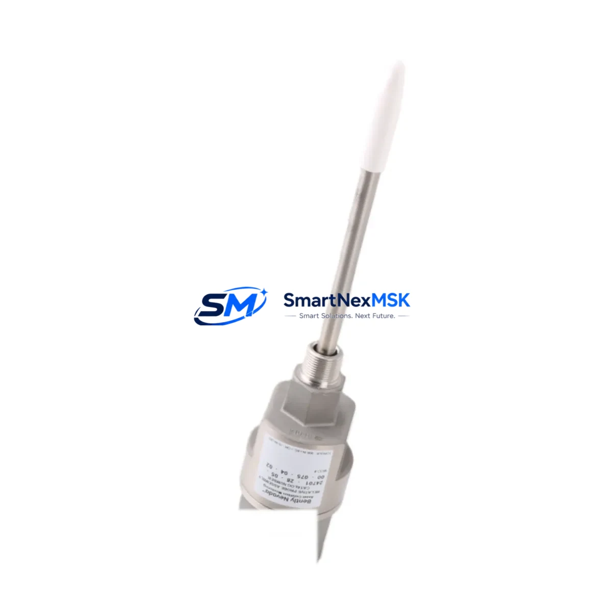
The Bently Nevada 24701-28-10-35-027-03-02 is an original proximity transducer housing assembly engineered for the 3300 XL Series continuous machinery monitoring system. Designed for critical rotating equipment applications — including turbines, compressors, pumps, and gearboxes — this component plays a central role in vibration and position measurement loops that protect high-value assets from catastrophic failure. When this part degrades or fails, the entire monitoring channel is compromised, leaving machinery unprotected and triggering unplanned shutdowns.
At SMARTNEXMSK, we stock the 24701-28-10-35-027-03-02 as a maintenance-ready spare, fully tested prior to shipment and backed by a 12-month warranty. Our inventory is sourced to support both emergency replacement and planned maintenance cycles, ensuring your facility can restore monitoring integrity without extended lead times.
Spare Maintenance Table
| Parameter | Specification / Detail |
|---|---|
| Part Number | 24701-28-10-35-027-03-02 |
| Brand | Bently Nevada |
| Series | 3300 XL Proximity Transducer System |
| Product Type | Proximity Transducer Housing Assembly |
| Measurement Function | Radial vibration, axial position, differential expansion |
| Compatible Systems | Bently Nevada 3300 XL Series monitoring racks |
| Signal Output | Eddy-current proximity signal (mV/mil or mV/µm) |
| Installation Type | Threaded housing, field-replaceable probe tip |
| Operating Environment | Industrial — turbine halls, compressor stations, pump skids |
| Origin | United States |
| Condition | Original spare, pre-shipment tested |
| Warranty | 12 Months |
| Lead Time | In stock — ships within 1–3 business days |
| Maintenance Recommendation | Replace as part of scheduled transducer calibration cycle or upon channel fault alarm |
Maintenance Planning for Continuous Operation
Replacing the 24701-28-10-35-027-03-02 in a live 3300 XL monitoring loop requires a systematic approach to avoid introducing new faults during the maintenance window. Maintenance engineers should treat this replacement as an opportunity to audit the entire measurement chain.
Begin by verifying the condition of the 3300 XL extension cable (typically the 330130 series) that connects the probe to the proximitor. Cable insulation degradation or connector corrosion is a common secondary fault that goes undetected until a new probe is installed and the channel still reads erratically. Simultaneously, inspect the 3300 XL proximitor/driver (such as the 3300/16 or 3300/20 series) mounted in the monitoring rack — a failing proximitor will produce incorrect gap voltage even with a new probe assembly in place.
Within the monitoring rack itself, check the 3500/42M Proximitor/Seismic Monitor or equivalent 3300-series monitor card for any latched alarms or configuration drift. If the facility uses a 3500/22M Transient Data Interface, confirm that the channel mapping still reflects the correct probe location and engineering units after the replacement. For systems integrated with a System 1 Evolution or System 1 Optimizer platform, re-validate the channel configuration and alarm setpoints post-installation.
On the power supply side, confirm that the 3500/15 Power Supply or equivalent rack power module is delivering stable DC voltage to the proximitor. Voltage sag under load is a known cause of intermittent proximity channel faults that mimic probe failure. If the control cabinet houses a 3300/55 Keyphasor Module, verify that the Keyphasor signal is clean and properly phased, as this reference signal affects all vibration and position measurements in the rack.
For facilities running older 3300 XL installations, this replacement is also an appropriate time to assess whether the 3300/20 Proximitor units in adjacent channels show signs of aging — elevated quiescent current draw or thermal discoloration on the housing are early indicators. Stocking a small buffer of 24701-series probe assemblies alongside compatible proximitor spares and extension cables is a proven strategy for reducing mean time to repair (MTTR) on critical machinery trains.
Site Replacement Workflow
Step 1 — Pre-replacement verification: Confirm the existing probe gap voltage using a calibrated voltmeter at the proximitor output terminals. Document the as-found reading before disconnecting any components. This baseline is essential for validating the new assembly after installation.
Step 2 — Safe isolation: Coordinate with the control room to bypass or inhibit the affected monitoring channel in the 3300 XL rack. Do not remove the probe while the channel is in active alarm state without first confirming bypass status with the DCS or safety system operator.
Step 3 — Physical replacement: Remove the 24701-28-10-35-027-03-02 housing assembly using the correct thread engagement procedure. Inspect the mounting boss on the bearing housing for thread damage or contamination. Install the replacement assembly to the manufacturer-specified gap (typically 50 mil / 1.27 mm for standard 3300 XL probes) and torque to specification.
Step 4 — Signal validation: With the new probe installed and the extension cable reconnected to the proximitor, measure the output gap voltage. The reading should fall within the linear range specified for the 3300 XL system (typically –10 VDC ±0.5 VDC at nominal gap). If the reading is outside range, re-check cable continuity and proximitor supply voltage before assuming probe fault.
Step 5 — Channel reinstatement: Remove the bypass, confirm alarm setpoints are active, and log the replacement in the equipment maintenance record. Update the spare parts inventory to trigger reorder of the consumed 24701-28-10-35-027-03-02 unit, maintaining buffer stock for the next maintenance cycle.
Spare Parts Support FAQ
Q1: Is the 24701-28-10-35-027-03-02 a direct drop-in replacement for older 3300 XL probe assemblies?
Yes. The 24701-28-10-35-027-03-02 is designed as a field-replaceable assembly within the 3300 XL proximity transducer system. It maintains the same thread form, cable connector interface, and electrical characteristics as the original factory-installed units, making it a direct replacement without requiring rack reconfiguration or re-cabling in standard installations.
Q2: What pre-shipment testing is performed on this spare?
Each 24701-28-10-35-027-03-02 unit shipped by SMARTNEXMSK undergoes functional verification including gap voltage linearity check and insulation resistance test. Units that do not meet OEM electrical specifications are quarantined and not offered for sale. A test report is available upon request for critical applications.
Q3: How should this part be stored if purchased for buffer stock?
Store in the original anti-static packaging in a dry, temperature-controlled environment (10–40°C, <80% RH non-condensing). Avoid proximity to strong magnetic fields or high-vibration areas within the storeroom. Inspect the probe tip and connector annually if held in long-term storage, and verify gap voltage performance before installation if stored for more than 24 months.
Q4: What does the 12-month warranty cover?
The 12-month warranty covers manufacturing defects and electrical performance failures under normal operating conditions. It does not cover damage resulting from incorrect installation gap, mechanical impact, chemical contamination, or operation outside the 3300 XL system’s specified voltage and temperature ranges. Warranty claims are processed with return of the defective unit and provision of installation documentation.
© 2026 SMARTNEXMSK. All rights reserved.
Original Source: https://smartnexmsk.com
Contact: sales@smartnexmsk.com | +86 18259474341


