Bently Nevada 3077-755A Retrofit-Ready Vibration Monitor for 3500 Series Control Systems
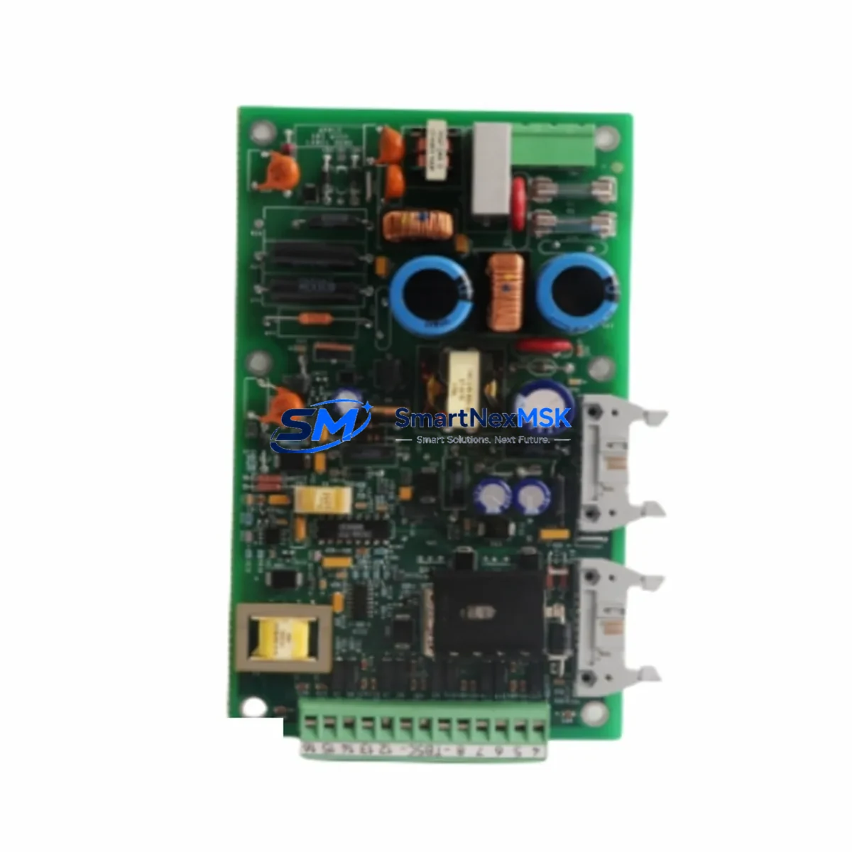
The Bently Nevada 3077-755A is a retrofit-ready vibration monitoring circuit board engineered for seamless integration into existing Bently Nevada 3500 Series machinery protection systems. As legacy installations age and OEM support for discontinued modules becomes increasingly limited, the 3077-755A provides a verified drop-in replacement path that preserves your existing rack architecture, wiring infrastructure, and monitoring logic — minimizing engineering rework and unplanned downtime.
This module is purpose-built for industrial environments where continuous vibration monitoring of rotating machinery — including turbines, compressors, pumps, and motors — is mission-critical. Whether you are replacing a failed board, upgrading a degraded system, or executing a planned modernization of your control cabinet, the 3077-755A delivers the signal conditioning, channel isolation, and output compatibility required to maintain operational continuity without full system replacement.
Upgrade Compatibility Table
| Parameter | Details |
|---|---|
| Primary SKU | 3077-755A |
| Compatible Replacement SKUs | 9907-147N, 5501-303L |
| Compatible Platform | Bently Nevada 3500 Series Machinery Protection System |
| Module Type | Vibration Monitor Circuit Board |
| Rack / Backplane Interface | 3500 Series standard backplane slot (I/O rack compatible) |
| Communication Protocol | 4–20 mA analog output; RS-232/RS-485 serial (system dependent) |
| Power Supply Requirement | Verify 3500 rack PSU capacity before installation; typical 24 VDC rail |
| Installation Type | Direct slot replacement — no bracket or adapter modification required |
| Retrofit Recommendation | Confirm channel address DIP switch settings match original module configuration |
| Commissioning Focus | Transducer wiring polarity, OK relay output, and alarm setpoint re-entry |
| Warranty | 12-Month Warranty — covers manufacturing defects and functional failure |
Retrofit Planning for Existing Automation Systems
Successful integration of the 3077-755A into a legacy 3500 Series system begins with a thorough pre-installation audit. Engineers should first verify that the 3500 Rack Power Supply — typically a 3500/15 Power Supply Module — can support the additional load introduced by the replacement board. Overloaded power rails are a common cause of intermittent faults during post-retrofit commissioning and should be ruled out before the new module is seated.
Terminal wiring from the existing 3500/20 Rack Interface Module or dedicated I/O terminal blocks should be documented and photographed before disconnection. The 3077-755A uses the same terminal pinout as its predecessors, but field wiring for proximity probes — including the 3300 XL 8mm Proximity Transducer and associated 3300 RAM Extension Cable — must be verified for correct polarity and shield grounding. Improper grounding at the transducer junction box is a frequent source of noise-induced false alarms after module replacement.
For systems that include a 3500/22M Transient Data Interface or a 3500/42M Proximitor/Seismic Monitor in the same rack, confirm that the module address settings on the 3077-755A match the slot assignment expected by the System 1 Evolution condition monitoring software or the legacy Bently Nevada Data Manager. Address conflicts between modules sharing the same rack will prevent the system from correctly mapping channel data to the HMI display or historian.
Where the existing control system interfaces with a DCS platform — such as a Honeywell Experion PKS or an Emerson DeltaV — via Modbus RTU or a 4–20 mA hardwired loop, the analog output scaling of the 3077-755A must be confirmed against the DCS input card’s engineering unit range. Rescaling may be required in the DCS configuration if the original module used a non-standard output range. This step is particularly important in systems where the vibration signal feeds directly into a safety instrumented function or a process shutdown interlock.
If the retrofit scope includes upgrading the 3500/01 Rack Configuration Module firmware or migrating rack configuration files, ensure that the new configuration is validated in a test environment before being loaded to the live rack. Configuration errors at this stage can cause all modules in the rack to go offline simultaneously, triggering a full machinery trip.
Downtime Control During System Migration
Minimizing production downtime during a 3077-755A replacement requires a structured hot-swap or planned-outage strategy. For systems where the 3500 rack supports online module replacement, the swap can be executed during a scheduled maintenance window without a full machinery shutdown — provided the replacement module is pre-configured with the correct channel address, alarm setpoints, and OK relay logic before installation.
Prior to removing the failed or end-of-life module, export the full rack configuration from the Rack Configuration Software (RCS) and save a timestamped backup. This file contains all channel parameters, alarm thresholds, transducer type assignments, and communication settings. Restoring from this backup after module replacement eliminates the need to manually re-enter setpoints and reduces the risk of configuration drift.
For systems without hot-swap capability, coordinate the replacement with the operations team to align with a planned process hold or equipment isolation window. Prepare the replacement 3077-755A in advance: verify the board revision, confirm the firmware version is compatible with the installed RCS version, and bench-test the module using a signal simulator to confirm OK relay operation and analog output linearity before taking the system offline. This pre-staging approach typically reduces on-site replacement time to under 30 minutes, keeping the maintenance window tight and the impact on production minimal.
After installation, perform a full channel check: confirm transducer OK status, verify gap voltage is within the acceptable range for the installed proximity probe, check that alarm and danger setpoints are correctly loaded, and validate that the System 1 or DCS historian is receiving clean data on all active channels. Document the as-left configuration and retain it with the equipment maintenance record.
Retrofit Support FAQ
Q1: Is the 3077-755A a direct replacement for the 9907-147N and 5501-303L?
Yes. The 3077-755A is functionally compatible with the 9907-147N and 5501-303L in standard 3500 Series rack configurations. Verify the module slot address and DIP switch settings match the original module before installation. No mechanical modification to the rack or backplane is required.
Q2: What commissioning steps are required after installation?
After seating the module, reload the rack configuration file via RCS, confirm transducer gap voltage and OK relay status on all assigned channels, re-enter or verify alarm and danger setpoints, and validate analog output signal levels at the DCS or control room receiver. A full functional test of the OK relay trip output is recommended before returning the machinery to service.
Q3: How do I verify wiring compatibility with my existing terminal blocks?
The 3077-755A uses the standard 3500 Series terminal block pinout. Compare the wiring diagram in the 3077-755A product manual against your as-built drawings. Pay particular attention to the shield drain wire termination point and the common reference for the proximity probe power supply. If the original wiring used a 3500/05 System Display and Reset Module for local indication, confirm the display interface wiring is also intact.
Q4: What does the 12-month warranty cover?
The 12-month warranty covers manufacturing defects and functional failure under normal operating conditions. Each unit undergoes pre-shipment functional testing to verify channel operation, OK relay response, and analog output accuracy. Warranty claims are supported by our technical team at sales@smartnexmsk.com. Damage resulting from incorrect installation, overvoltage, or environmental exposure outside the module’s rated specifications is excluded.
© 2026 SMARTNEXMSK. All rights reserved.
Original Source: https://smartnexmsk.com
Contact: sales@smartnexmsk.com | +86 18259474341


