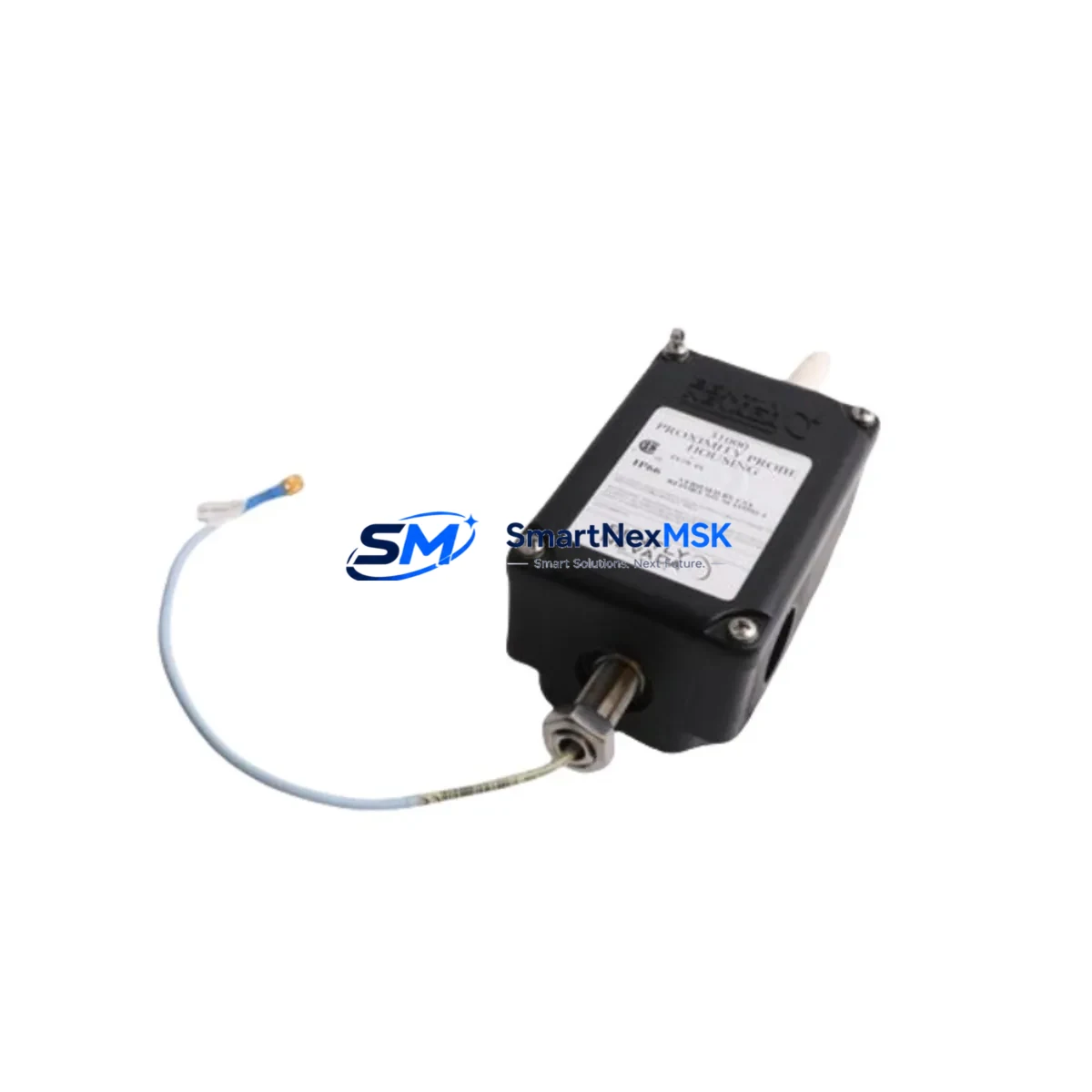
Bently Nevada 31000-16-05-00-65-03-02 Spare 31000 Series: Precision Spare Parts Replacement for Industrial Downtime Control
The Bently Nevada 31000-16-05-00-65-03-02 is an original proximity probe housing unit from the 31000 Series eddy current sensing system — one of the most widely deployed non-contact vibration and position measurement platforms in rotating machinery protection. Designed for continuous operation in turbines, compressors, pumps, and gearboxes, this component plays a critical role in machinery health monitoring and predictive maintenance programs across oil & gas, power generation, petrochemical, and heavy industrial facilities.
When this probe fails or degrades, the entire vibration monitoring loop is compromised. Unplanned downtime in rotating machinery environments can cost thousands of dollars per hour. Maintaining a verified spare of the 31000-16-05-00-65-03-02 in your critical spare parts inventory is a fundamental risk-mitigation strategy for any maintenance or reliability engineering team.
This listing provides an original, tested, and warranty-backed replacement unit — ready for immediate site installation with full compatibility confirmation against the 31000 Series system architecture.
Spare Maintenance Table
| Parameter | Specification |
|---|---|
| SKU / Part Number | 31000-16-05-00-65-03-02 |
| Brand | Bently Nevada |
| Series | 31000 Series |
| Product Type | Proximity Probe (Eddy Current Sensor) |
| Sensing Technology | Eddy Current / Non-Contact |
| Typical Application | Shaft vibration, axial position, differential expansion monitoring |
| Compatible Systems | Bently Nevada 3300, 3500 Series monitoring systems |
| Installation Type | Threaded housing, direct mount |
| Operating Environment | Industrial — turbines, compressors, pumps, gearboxes |
| Origin | USA |
| Condition | Original / New |
| Warranty | 12 Months |
| Lead Time | In stock — ships within 24–48 hours |
| Testing | Function-tested prior to dispatch |
Maintenance Planning for Continuous Operation
Replacing the 31000-16-05-00-65-03-02 is rarely an isolated task. Maintenance engineers performing a planned or emergency replacement of this proximity probe should conduct a concurrent inspection of the full vibration monitoring loop to prevent repeat failures and ensure system integrity.
Begin with the extension cable connecting the probe to the proximitor. The 3300 XL 8mm Extension Cable is a common wear item in high-vibration environments — inspect for jacket abrasion, connector corrosion, and continuity. Next, verify the proximitor/driver unit (such as the 3300 XL Proximitor Sensor) for correct gap voltage output, typically –10 VDC at the calibrated gap. A drifting proximitor will produce false vibration readings even with a new probe installed.
Check the signal conditioning barrier or Zener barrier in the intrinsically safe circuit if the probe is installed in a hazardous area. Degraded barriers introduce signal noise that mimics mechanical faults. Inspect the terminal block and field wiring in the junction box — loose terminations on the coaxial signal cable are a leading cause of intermittent probe faults.
At the monitoring rack level, inspect the 3500/40M Proximitor Monitor or equivalent I/O module for alarm setpoint integrity and channel calibration. If the system uses a 3500/22M Transient Data Interface, confirm that the channel mapping and engineering unit scaling remain correct after probe replacement. For facilities running System 1 Evolution condition monitoring software, update the asset configuration to reflect the new probe installation date and recalibrate the baseline vibration signature.
In control cabinet inspections, also verify the 24 VDC power supply feeding the proximitor rail — voltage sag under load is a common but overlooked cause of probe system instability. Fuse integrity on the proximitor supply circuit should be confirmed, and any signal isolators in the loop should be tested for output linearity. For legacy systems approaching end-of-life, consider stocking the 3300 RAM Module and 3500 Rack Interface Module as part of a comprehensive critical spare strategy alongside the 31000-16-05-00-65-03-02.
Site Replacement Workflow
Step 1 — Pre-Replacement Verification: Confirm the replacement SKU 31000-16-05-00-65-03-02 matches the installed probe’s thread size, body length, and cable length. Cross-reference against the original engineering drawing or the machine OEM spare parts list. Verify gap voltage specification matches the proximitor driver in use.
Step 2 — Safe Isolation: Follow site LOTO (Lockout/Tagout) procedures. Bypass the vibration channel at the monitoring rack to prevent spurious trips during probe removal. Document the existing gap voltage reading before disconnection.
Step 3 — Probe Removal and Inspection: Remove the probe carefully to avoid thread damage. Inspect the probe tip for impact marks or contamination. Clean the probe bore in the bearing housing. Inspect the extension cable connector for pin damage or moisture ingress.
Step 4 — Installation and Gap Setting: Install the new 31000-16-05-00-65-03-02 and set the air gap per the calibration specification (typically 1.0–1.5 mm for standard 8mm probes). Verify gap voltage at the proximitor output using a calibrated voltmeter. Reconnect the extension cable and confirm signal continuity.
Step 5 — System Recommission: Remove the channel bypass at the monitoring rack. Confirm the vibration reading is within the expected baseline range. Log the replacement in the CMMS with the new probe serial number and installation date. Update the spare parts inventory to trigger reorder of a replacement spare unit.
This workflow minimizes downtime, ensures system compatibility, and maintains the integrity of the machinery protection system — reducing the risk of undetected mechanical faults during the post-maintenance period.
Spare Parts Support FAQ
Q1: Is the 31000-16-05-00-65-03-02 compatible with both the 3300 and 3500 Series monitoring systems?
Yes. The 31000 Series proximity probes are designed for use with Bently Nevada 3300 and 3500 Series monitoring racks when paired with the correct proximitor driver and extension cable. Always verify the gap voltage specification and cable length match your installed system configuration before ordering.
Q2: What is the recommended spare parts stocking strategy for this probe?
For critical rotating machinery (turbines, compressors, main pumps), reliability engineers typically recommend holding a minimum of one-for-one critical spares — one spare probe per installed probe on critical trains. For non-critical applications, a pooled spare covering 20–30% of installed population is a common industry practice. Given the lead times for OEM procurement, maintaining at least one verified spare of the 31000-16-05-00-65-03-02 on-site is strongly advised.
Q3: How is the unit tested before shipment?
Every 31000-16-05-00-65-03-02 unit is function-tested prior to dispatch. Testing includes coil resistance verification, insulation integrity check, and gap voltage output confirmation using a calibrated proximitor driver. A test report is available upon request. Units are packaged to prevent tip damage and electrostatic discharge during transit.
Q4: What warranty and after-sales support is provided?
All units carry a 12-month warranty covering manufacturing defects and functional failure under normal operating conditions. Our technical team provides compatibility verification support, installation guidance, and post-installation troubleshooting assistance. Long-term supply agreements are available for facilities requiring scheduled replacement programs or multi-unit procurement.
© 2026 SMARTNEXMSK. All rights reserved.
Original Source: https://smartnexmsk.com
Contact: sales@smartnexmsk.com | +86 18259474341


