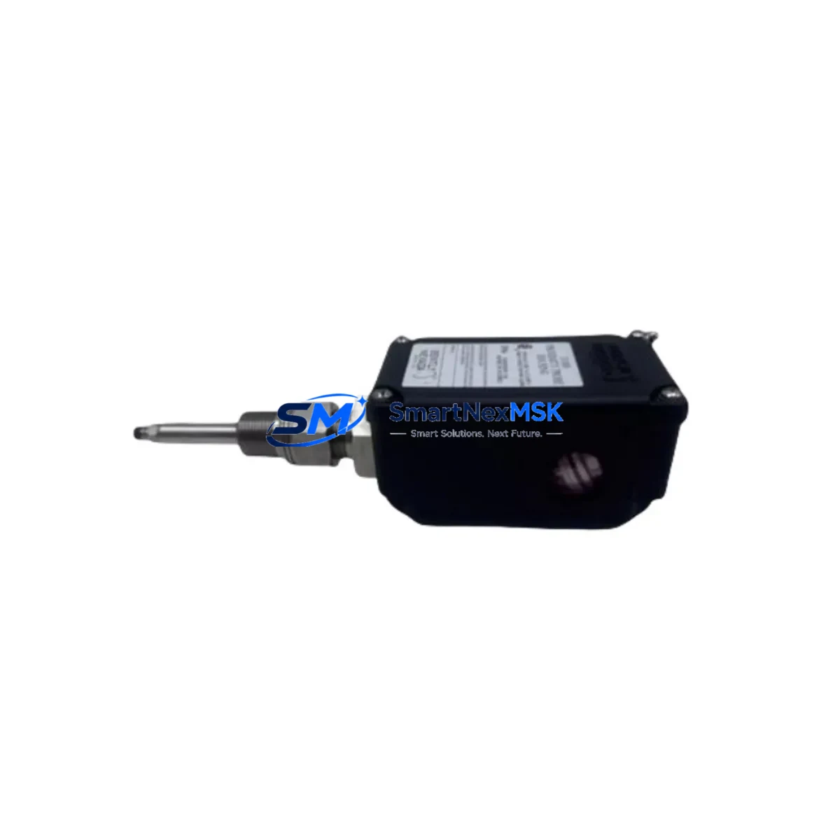
Bently Nevada 31000-16-10-00-154-00-02 Retrofit-Ready Proximity Probe Housing for 3300 XL Control Systems
The Bently Nevada 31000-16-10-00-154-00-02 is a precision proximity probe housing assembly engineered for seamless integration into Bently Nevada 3300 XL Series vibration monitoring and machinery protection systems. As legacy industrial facilities face increasing pressure to modernize aging control infrastructure, this component serves as a critical retrofit solution — enabling engineers to replace discontinued or worn proximity probe assemblies without redesigning the entire monitoring loop or interrupting long-running machinery protection programs.
Designed to meet the dimensional and electrical specifications of the original Bently Nevada 3300 XL platform, the 31000-16-10-00-154-00-02 housing supports eddy-current proximity sensing applications across turbines, compressors, pumps, and rotating machinery where continuous shaft position and vibration data are essential for predictive maintenance and trip protection. Its compatibility with the 3300 XL proximitor/seismic interface module ensures that existing signal conditioning chains, including the 3300/16 proximitor and 3300/20 proximitor, remain fully operational after replacement — eliminating the need for recalibration of the entire measurement chain.
Upgrade Compatibility Table
| Parameter | Details |
|---|---|
| SKU / Part Number | 31000-16-10-00-154-00-02 |
| Brand | Bently Nevada |
| Compatible Series | Bently Nevada 3300 XL Series |
| Component Type | Proximity Probe Housing Assembly |
| Probe Tip Diameter | 8 mm (standard 3300 XL format) |
| Cable Length | Per original specification (confirm with system drawing) |
| Connector Interface | Compatible with 3300 XL proximitor input terminals |
| Installation Type | Direct drop-in replacement; no bracket modification required |
| Communication Compatibility | Analog 4–20 mA / voltage output; compatible with 3500 Series rack I/O |
| Replacement Recommendation | Suitable for replacing discontinued 31000-series probe housings in 3300 XL loops |
| Commissioning Notes | Verify gap voltage at proximitor output; confirm linear range per system documentation |
| Warranty | 12-Month Warranty — covers manufacturing defects and functional failure under normal operating conditions |
Retrofit Planning for Existing Automation Systems
When planning a retrofit involving the 31000-16-10-00-154-00-02, engineers must account for the full measurement chain within the 3300 XL monitoring loop. The probe housing interfaces directly with the proximitor module — typically a 3300/16 or 3300/20 proximitor — which conditions the raw eddy-current signal into a usable voltage or 4–20 mA output for the 3500 Series rack-based monitoring system. Before installation, confirm that the existing proximitor extension cable (commonly a 330130 or 330180 series cable) is undamaged and correctly routed, as cable condition directly affects gap calibration accuracy.
In control cabinet upgrades where the 3500/22M transient data interface or 3500/42M proximitor I/O module is installed, verify that the new probe housing’s sensitivity factor (V/mm) matches the proximitor’s configured scale factor. Mismatched sensitivity will cause erroneous vibration readings and may trigger false machinery trips. For facilities migrating from older 3300 Series racks to the 3500 Series platform, the 31000-16-10-00-154-00-02 housing remains compatible provided the proximitor model is updated accordingly.
I/O expansion projects that add new measurement points to an existing 3500 rack should also account for the 3500/20 rack interface module and available backplane slots. When the control system includes a System 1 Evolution software platform for data acquisition and trending, ensure that the new probe channel is correctly mapped in the software configuration before commissioning. For facilities using a DCS integration layer — such as an Emerson DeltaV or Honeywell Experion PKS — confirm that the 4–20 mA signal from the proximitor is correctly scaled at the DCS analog input card to reflect engineering units (µm or mil peak-to-peak).
HMI screens tied to the vibration monitoring loop should be reviewed to confirm that tag names, alarm setpoints, and display ranges reflect the new probe’s installation position and measurement axis. In multi-shaft machinery trains, also verify that the Keyphasor module — typically a 3500/25 or 3300/25 Keyphasor — remains correctly phased relative to the new probe location to ensure accurate 1X and 2X vector data.
Downtime Control During System Migration
Minimizing unplanned downtime during proximity probe replacement is a primary concern for maintenance teams operating continuous-process machinery. The 31000-16-10-00-154-00-02 is designed as a direct mechanical and electrical replacement, which means the physical swap can typically be completed within a planned maintenance window without requiring changes to the proximitor wiring, terminal block assignments, or DCS tag configuration.
To protect existing program logic, document the current gap voltage reading at the proximitor output before removing the old probe. This baseline value — typically between −10 VDC and −18 VDC for a correctly gapped 3300 XL probe — serves as the reference for post-installation verification. After installing the new housing and setting the mechanical gap per the system’s installation drawing, re-measure the output voltage and confirm it falls within the linear range specified for the proximitor model in use.
For facilities where the 3500 rack is configured with a bypass key or inhibit function, activate the channel inhibit on the affected measurement point before beginning the swap. This prevents the monitoring system from issuing a spurious trip or alarm during the brief period when the probe is disconnected. Once the new probe is installed and gap-verified, release the inhibit and confirm that the channel returns to normal monitoring status in both the 3500 rack display and the System 1 software trend screen.
Where machinery cannot be taken offline, a hot-standby approach using a parallel redundant probe channel — if the rack configuration supports dual-probe voting logic — allows the replacement to proceed without interrupting the protection function. All replacement activities should be documented in the facility’s maintenance management system, with pre- and post-installation gap voltage readings recorded for traceability and warranty validation.
Retrofit Support FAQ
Q1: Is the 31000-16-10-00-154-00-02 a direct replacement for the original Bently Nevada part?
Yes. This housing assembly is manufactured to the dimensional and electrical specifications of the original 31000-16-10-00-154-00-02 and is intended as a drop-in replacement within the 3300 XL measurement loop. No bracket modification or rewiring is required in standard installations.
Q2: What commissioning checks are required after installation?
After mechanical installation, verify the probe-to-target gap using the proximitor output voltage. Confirm the voltage falls within the linear range for your proximitor model (typically −10 VDC to −18 VDC). Check alarm and trip setpoints in the 3500 rack configuration and confirm the channel is active and reading correctly in the System 1 software or connected DCS.
Q3: Is the probe housing compatible with both 3300 XL and 3500 Series monitoring systems?
The 31000-16-10-00-154-00-02 housing is designed for the 3300 XL proximitor interface. When used with a 3500 Series rack, compatibility depends on the proximitor module installed (e.g., 3500/42M). Confirm the proximitor model and sensitivity factor before installation to ensure correct signal conditioning.
Q4: What does the 12-month warranty cover?
The 12-month warranty covers manufacturing defects and functional failure under normal operating conditions from the date of shipment. Each unit undergoes pre-shipment functional testing. Warranty claims require documentation of installation conditions and, where applicable, pre- and post-installation gap voltage readings.
© 2026 SMARTNEXMSK. All rights reserved.
Original Source: https://smartnexmsk.com
Contact: sales@smartnexmsk.com | +86 18259474341


