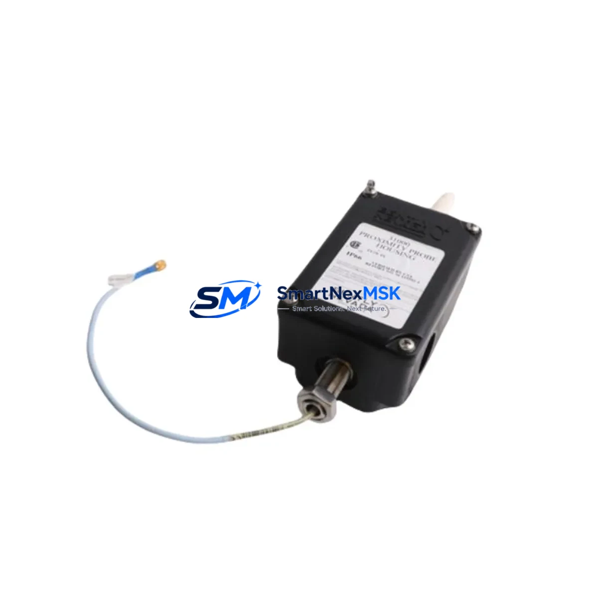
Bently Nevada 31000-26-05-00-100-03-02 3300 XL Probe Housing: Compatible Retrofit & Smooth System Upgrade
The Bently Nevada 31000-26-05-00-100-03-02 is a proximity probe housing assembly engineered for the 3300 XL Series vibration monitoring platform. As legacy Bently Nevada systems age and original spare parts become increasingly scarce, this component serves as a critical retrofit solution for facilities maintaining turbomachinery protection systems, compressor trains, and rotating equipment monitoring networks. Whether you are replacing a failed housing on an existing 3300 XL rack or upgrading a discontinued 3300/05 or 3300/16 monitor configuration, this assembly provides the mechanical and electrical interface required for uninterrupted proximity measurement continuity.
Before initiating a replacement, engineers should verify the following parameters against the existing installation: probe tip diameter and gap voltage calibration range (typically -10 VDC to -18 VDC for standard Bently Nevada eddy-current probes), extension cable length and connector type (3300 XL systems commonly use 9000-series extension cables), driver/proximitor module compatibility (such as the 3300/55 or 3300/65 proximitor), and terminal block wiring assignments within the monitor chassis. Mismatched housing geometry or incorrect gap settings will result in erroneous vibration readings and potential false trips on the machinery protection system.
When integrating the 31000-26-05-00-100-03-02 into an existing rack, confirm that the backplane slot assignment and module address configuration align with the original channel mapping stored in the System 1 condition monitoring software or equivalent historian. If the facility uses a 3500 Series rack as part of a parallel upgrade path, note that the 3500/42M Proximitor Monitor accepts compatible probe inputs but requires re-termination at the I/O module and updated channel configuration in the 3500 Rack Configuration Software.
Upgrade Compatibility Table
| Parameter | Details |
|---|---|
| Compatible Series | Bently Nevada 3300 XL, 3300/05, 3300/16, 3300/55 |
| Replacement For | Discontinued 3300 XL proximity probe housing assemblies |
| Mounting Interface | Standard 3300 XL rack backplane slot |
| Communication Compatibility | Eddy-current proximity signal (analog, -24 VDC bias) |
| Installation Requirement | Verify gap voltage, extension cable, and proximitor model |
| Commissioning Note | Re-calibrate gap after installation; confirm channel address |
| Warranty | 12 Months from date of shipment |
| Origin | USA |
Retrofit Planning for Existing Automation Systems
Successful integration of the 31000-26-05-00-100-03-02 into a live plant environment requires a structured retrofit plan that accounts for the full signal chain. The proximity measurement loop begins at the probe tip and passes through the extension cable — typically a 330130-series extension cable — before reaching the proximitor module. The proximitor, such as the 3300/55 Proximitor or the newer 3300/65 Proximitor, conditions the raw eddy-current signal into a calibrated voltage output that the monitor module reads as displacement in mils or micrometers.
Within the 3300 XL rack, the 3300/20 Power Supply provides the regulated -24 VDC required by the proximitor circuit. Engineers replacing the housing assembly should confirm that the power supply output is within specification before energizing the new component, as voltage sag can cause measurement offset errors. The rack’s 3300/10 Rack Interface Module manages communication between the monitor modules and the plant DCS or safety instrumented system (SIS), and any channel reconfiguration must be reflected in the rack interface settings.
For facilities migrating from the 3300 XL platform to the 3500 Series, the retrofit path typically involves installing a 3500/42M Proximitor Monitor in a new 3500 rack alongside a 3500/20 Power Supply, re-terminating field wiring at the 3500/32 4-Channel Relay Module I/O terminals, and updating trip setpoints in the 3500 Rack Configuration Software. During this transition, the 31000-26-05-00-100-03-02 housing can remain in service on the legacy 3300 XL rack, allowing a phased cutover that avoids a full system shutdown. HMI screens connected via Modbus or OPC-DA to the System 1 software will require tag remapping once the 3500 rack is brought online.
I/O expansion during a control cabinet upgrade may also involve adding a 3300/46 Dual Voting Logic Module to handle redundant trip logic, or integrating a 3300/95 Communication Gateway for Ethernet-based data transfer to the plant historian. All wiring changes within the control cabinet should be documented against the original loop drawings, and terminal block assignments verified with a calibrated multimeter before re-energizing the system.
Downtime Control During System Migration
Minimizing unplanned downtime during a proximity probe housing replacement or broader 3300 XL system migration requires careful pre-staging and a clear sequence of operations. Begin by downloading and archiving the current rack configuration from the System 1 software or the 3500 Rack Configuration Software before any hardware is disturbed. This configuration backup preserves all channel setpoints, alarm thresholds, and trip multiplier settings, and serves as the restoration baseline if commissioning reveals unexpected behavior.
Where process conditions permit, perform the housing swap during a scheduled maintenance window with the machinery at rest. If a hot-swap is required on a running machine, coordinate with the control room to temporarily inhibit the affected channel’s trip output — using the monitor’s front-panel inhibit function or a software bypass in the SIS — before disconnecting the probe extension cable. This prevents a spurious trip signal from reaching the turbine protection relay or the emergency shutdown system.
After installing the 31000-26-05-00-100-03-02 housing and reconnecting the extension cable, perform a static gap check using a digital voltmeter at the proximitor output terminals. The gap voltage should fall within the linear range specified on the probe calibration certificate, typically between -10.0 VDC and -12.0 VDC for a standard 5 mm probe at nominal gap. Once the static check is confirmed, restore the channel from inhibit, observe the dynamic vibration reading during machine run-up, and verify that the 1X and 2X amplitude trends are consistent with the pre-replacement baseline stored in the historian. Document the as-left gap voltage and vibration baseline in the plant maintenance management system (CMMS) before closing the work order.
Retrofit Support FAQ
Q1: Is the 31000-26-05-00-100-03-02 a direct drop-in replacement for the original 3300 XL proximity probe housing?
A: Yes, this assembly is dimensionally and electrically compatible with the standard 3300 XL rack slot. However, always verify the probe tip diameter, extension cable connector type, and proximitor model number against your existing installation before ordering, as minor sub-variants exist within the 3300 XL product family.
Q2: What commissioning steps are required after installation?
A: After mechanical installation, perform a static gap voltage check at the proximitor output terminals, confirm the channel address matches the rack configuration file, restore any software bypasses, and validate dynamic vibration readings during machine run-up against the pre-replacement baseline. Update the CMMS with as-left gap voltage and calibration date.
Q3: Can this housing be used in a 3500 Series rack during a platform migration?
A: The 31000-26-05-00-100-03-02 is designed for the 3300 XL mechanical interface. For 3500 Series installations, the appropriate probe and housing assembly must be selected from the 3500-compatible product range. During a phased migration, the 3300 XL housing can remain in service on the legacy rack while the 3500 rack is commissioned in parallel.
Q4: What warranty coverage is provided, and how is pre-shipment testing conducted?
A: All units carry a 12-month warranty from the date of shipment. Prior to dispatch, each assembly undergoes functional verification including dimensional inspection, connector integrity check, and electrical continuity test. A test report is available upon request. Units are shipped in anti-static packaging with full traceability documentation.
© 2026 SMARTNEXMSK. All rights reserved.
Original Source: https://smartnexmsk.com
Contact: sales@smartnexmsk.com | +86 18259474341


