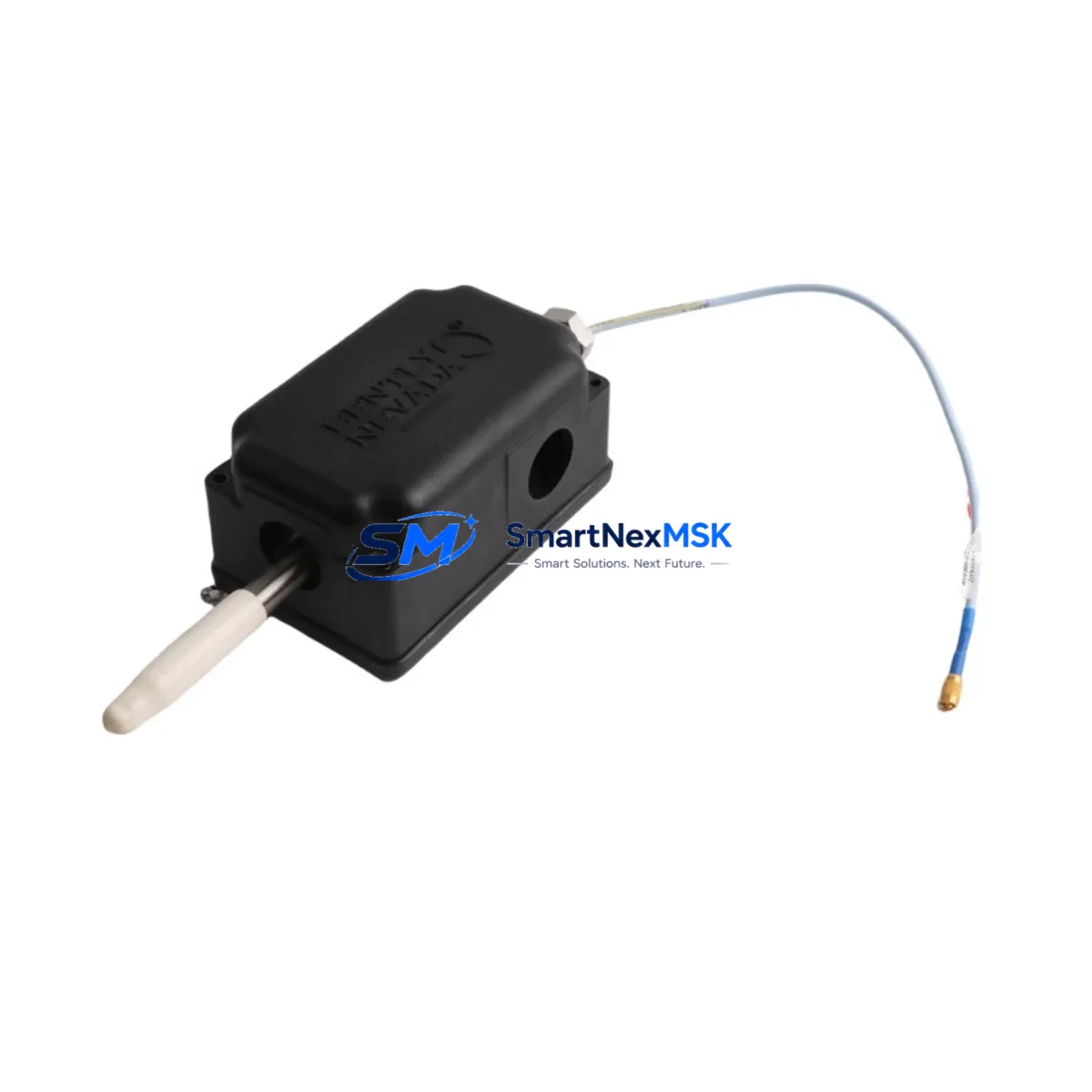
Bently Nevada 31000-28-05-00-024-01-02 Retrofit-Ready Proximity Probe for 3300 XL Control Systems
The Bently Nevada 31000-28-05-00-024-01-02 is a 28mm proximity probe engineered for the 3300 XL Series continuous machinery monitoring platform. As legacy 3300 Series installations reach end-of-service life, this probe serves as the primary retrofit solution for facilities transitioning from discontinued 3300 standard probes to the extended-range 3300 XL architecture. With a 24-inch (approximately 610mm) armored extension cable and a 2-meter (02) interconnect cable, this probe assembly is dimensionally and electrically compatible with existing conduit runs, junction boxes, and field wiring in most rotating machinery monitoring installations.
Industrial sites operating steam turbines, gas compressors, centrifugal pumps, and large induction motors rely on the 3300 XL system for real-time radial vibration, axial position, and speed measurement. When the original 3300 standard probes are no longer available through OEM channels, the 31000-28-05-00-024-01-02 provides a verified drop-in replacement path that preserves existing Bently Nevada 3300 XL Proximitor® sensor signal conditioning, eliminates the need for recalibration of the 3300 XL monitor cards, and maintains compliance with API 670 machinery protection standards.
Upgrade Compatibility Table
| Parameter | 31000-28-05-00-024-01-02 (This Unit) | Legacy 3300 Standard Probe | Retrofit Notes |
|---|---|---|---|
| Probe Tip Diameter | 28mm | 25mm / 28mm (varies) | Verify existing bore diameter before installation |
| Extension Cable Length | 24 inches (610mm) | Varies by suffix | Match conduit run; re-terminate if needed |
| Interconnect Cable Length | 2 metres | Varies | Confirm Proximitor® input terminal reach |
| Compatible Proximitor® | 3300 XL 8mm / 11mm / 25mm / 28mm | 3300 Standard Proximitor® | 3300 XL Proximitor® required for XL probes |
| Monitor Compatibility | 3300/16 Dual Voting, 3300/20 Radial Vibration | 3300/16, 3300/20 | No monitor card replacement required |
| Communication Protocol | Analog 4–20mA / voltage output via monitor | Same | No protocol migration required |
| Installation Standard | API 670 4th/5th Edition | API 670 | Full compliance maintained |
| Warranty | 12 Months | OEM warranty expired | Covered from date of shipment |
Retrofit Planning for Existing Automation Systems
A successful retrofit of the 31000-28-05-00-024-01-02 into an operating machinery protection system requires systematic pre-installation planning. Begin by auditing the existing rack configuration: identify the 3300 XL monitor chassis, confirm the installed Proximitor® sensor model (typically a 3300 XL 28mm Proximitor® mounted in a field junction box), and document the current gap voltage reading at the Proximitor® output terminals. This baseline reading — typically between -10 VDC and -18 VDC for a properly gapped 28mm probe — will serve as the acceptance criterion after the new probe is installed and gapped.
Before removing the old probe, photograph or record the terminal wiring at the Proximitor® sensor: the three-wire connection (positive supply, negative supply, and output signal) must be re-terminated identically on the replacement unit. If the existing installation uses a 3300 XL 8-Channel Temperature Monitor or a 3300/55 Keyphasor® module in the same rack, confirm that the rack power supply — commonly a 3300/05 Power Supply or equivalent — has sufficient current headroom to support the probe and Proximitor® combination without voltage droop on the -24 VDC bus.
For facilities running a System 1® condition monitoring software platform, the probe channel configuration (transducer scale factor, full-scale range, and alert/danger setpoints) is stored in the System 1® database and does not need to be re-entered after a like-for-like probe replacement. However, if the retrofit involves changing from a 25mm probe to a 28mm probe, the transducer scale factor must be updated in both the 3300 XL monitor card and the System 1® channel configuration to reflect the correct mV/mil or mV/µm sensitivity.
In installations where the 3300 XL rack communicates upstream to a DCS or SCADA system via a 3300/93 Communication Gateway or a Modbus TCP interface card, no changes to the communication link are required for a probe-level replacement. The gateway continues to pass vibration, position, and speed data to the host system — whether a Honeywell Experion PKS, Emerson DeltaV, or ABB 800xA platform — without interruption, provided the monitor card remains powered during the probe swap using a hot-swap procedure where plant safety rules permit.
Where hot-swap is not permitted, coordinate the probe replacement with the plant’s planned maintenance window. Prepare a 3300 XL Proximitor® sensor as a pre-staged spare, along with the required armored conduit fittings, cable glands, and terminal ferrules. Having a Bently Nevada 330130 or 330180 series extension cable on hand as a backup ensures that any conduit length discrepancy can be resolved on-site without delaying restart.
Downtime Control During System Migration
Minimizing unplanned downtime during a proximity probe retrofit requires a structured change-management approach. The most effective strategy is to pre-configure and bench-test the replacement 31000-28-05-00-024-01-02 assembly before the maintenance window begins. Connect the probe and its Proximitor® sensor to a portable -24 VDC bench supply, insert a steel target at the nominal gap distance (typically 1.0mm to 1.5mm for a 28mm probe), and verify that the output voltage falls within the expected linear range. Document this bench gap voltage as the pre-installation reference.
During the actual swap, use a non-sparking probe wrench to remove the old probe from the bearing housing, taking care not to disturb the Keyphasor® probe or any adjacent temperature sensors mounted in the same housing. Re-gap the new probe to the documented nominal gap, tighten the locknut to the torque specification in the Bently Nevada installation manual, and re-terminate the extension cable at the Proximitor® junction box. Power the Proximitor® and confirm the output voltage matches the bench reference within ±0.5 VDC before releasing the monitor channel from bypass.
Throughout the swap, the 3300 XL monitor card should be placed in bypass mode — not powered down — so that the remaining channels in the rack (axial position, second radial channel, speed) continue to protect the machine. This approach preserves the original program logic in the monitor, maintains all setpoint configurations, and keeps the DCS alarm annunciation active for the unaffected channels. Once the replaced channel is verified and released from bypass, perform a full channel functional test: apply a known vibration signal using a calibrated signal simulator and confirm that the monitor card, System 1® display, and DCS faceplate all reflect the correct engineering units and alarm states before returning the machine to service.
Retrofit Support FAQ
Q1: Is the 31000-28-05-00-024-01-02 a direct replacement for the discontinued 3300 standard 28mm probe?
A: Yes, for installations that have already upgraded to the 3300 XL Proximitor® sensor. The 3300 XL probe and Proximitor® are a matched system; if your site still uses the original 3300 standard Proximitor®, the Proximitor® must also be replaced with the 3300 XL equivalent before installing this probe.
Q2: Do I need to recalibrate the 3300 XL monitor card after installing this probe?
A: Not for a like-for-like 28mm replacement. The transducer scale factor, gap voltage reference, and alert/danger setpoints stored in the monitor card remain valid. Recalibration is only required if you are changing probe tip diameter or Proximitor® model.
Q3: What wiring checks should I perform before powering the new probe?
A: Verify continuity and insulation resistance on all three conductors (supply positive, supply negative, output signal) from the probe tip to the Proximitor® terminals. Confirm that the shield drain wire is grounded at one end only (typically at the Proximitor® enclosure) to avoid ground loops that can introduce noise into the vibration signal.
Q4: What does the 12-month warranty cover, and how is it validated?
A: The 12-month warranty covers manufacturing defects in the probe body, cable assembly, and connector. Each unit shipped by SMARTNEXMSK undergoes outgoing inspection including continuity, insulation resistance, and sensitivity verification. Warranty is activated from the date of shipment and is supported by the test record included with each unit. Contact sales@smartnexmsk.com for warranty claims or technical support.
© 2026 SMARTNEXMSK. All rights reserved.
Original Source: https://smartnexmsk.com
Contact: sales@smartnexmsk.com | +86 18259474341


