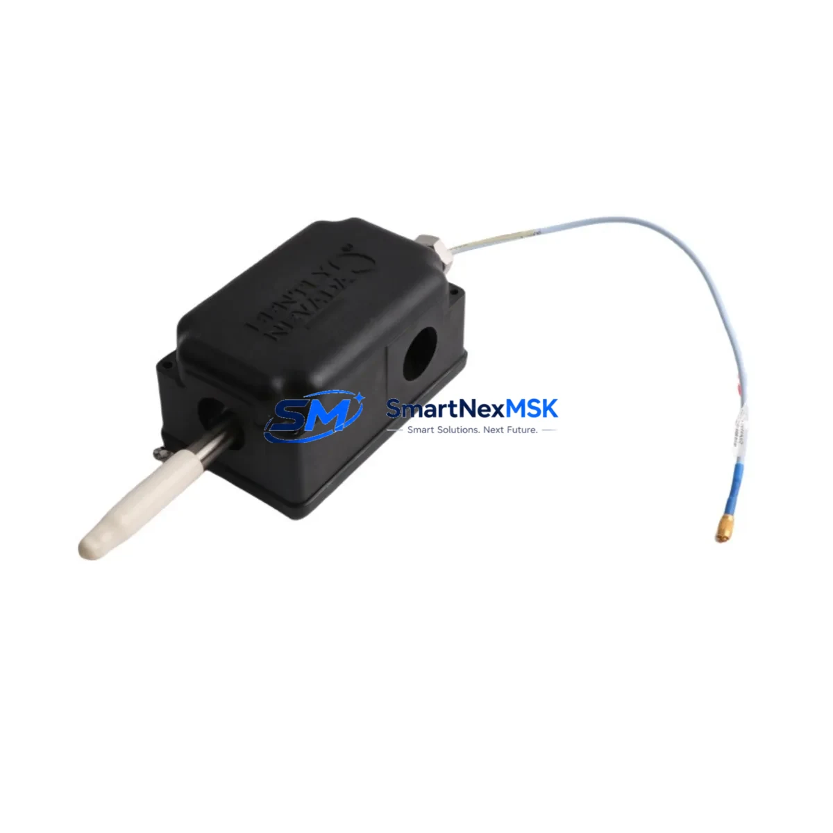
Bently Nevada 31000-28-10-00-133-03-02 Retrofit-Ready Proximity Probe for 3300 XL Control Systems
The Bently Nevada 31000-28-10-00-133-03-02 is a precision proximity probe housing assembly engineered for seamless integration into legacy 3300 XL vibration monitoring systems. As aging machinery protection platforms approach end-of-life or face discontinued spare parts availability, this unit provides a verified drop-in replacement path that preserves existing wiring, signal conditioning chains, and Bently Nevada System 1 software configurations without requiring panel redesign or re-engineering of the monitoring loop.
Industrial facilities operating rotating equipment — including steam turbines, gas compressors, centrifugal pumps, and large induction motors — rely on the 3300 XL platform for continuous shaft displacement and vibration monitoring. When the original probe housing assembly degrades or becomes unavailable through OEM channels, the 31000-28-10-00-133-03-02 offers a fully tested, specification-matched alternative that maintains API 670 compliance and supports existing Keyphasor signal routing without modification to the 3300 XL monitor rack or the 3300/16 I/O module assignments.
Before completing a retrofit installation, engineers should verify the following parameters against the existing system documentation: supply voltage compatibility with the 3300 XL proximitor power rail (typically –24 VDC), coaxial cable impedance and extension cable length within the calibrated range, target material and gap voltage at the nominal operating clearance, and the probe tip-to-target geometry relative to the shaft journal. The 31000-28-10-00-133-03-02 uses the standard Bently Nevada 8 mm probe body format, making it directly interchangeable with earlier-generation housings mounted on the same bearing bracket without re-drilling or adapter plates.
Upgrade Compatibility Table
| Parameter | Details |
|---|---|
| SKU / Part Number | 31000-28-10-00-133-03-02 |
| Compatible Platform | Bently Nevada 3300 XL Vibration Monitoring System |
| Probe Body Format | 8 mm standard, API 670 compliant |
| Supply Voltage | –24 VDC (3300 XL proximitor rail) |
| Output Signal | –200 mV/mil (–7.87 V/mm) nominal scale factor |
| Extension Cable Interface | Standard Bently Nevada coaxial, 5 m / 9 m calibrated lengths |
| Mounting Interface | Direct replacement — no adapter plate required |
| Communication Compatibility | Compatible with System 1 software via existing 3300/16 I/O module |
| Replacement Recommendation | Drop-in for discontinued OEM housing; verify gap voltage after installation |
| Commissioning Checkpoint | Gap voltage, scale factor verification, OK relay status in 3300 XL monitor |
| Warranty | 12-Month Warranty — covers manufacturing defects and signal performance |
Retrofit Planning for Existing Automation Systems
A successful retrofit of the 31000-28-10-00-133-03-02 into an operating plant begins well before the maintenance window opens. The engineering team should pull the existing loop drawing to confirm the extension cable part number — typically a Bently Nevada 330130 series cable — and verify that the total probe-plus-extension length falls within the calibrated range for the installed 3300 XL proximitor, such as the 330180-X1-05 or 330180-X1-09 proximitor module. Mismatched cable lengths are the most common source of scale factor error after a probe housing swap.
The 3300 XL monitor rack should be inspected for available I/O capacity. If the existing 3300/16 I/O module is fully allocated, the retrofit plan may need to include a spare channel reassignment or, in larger panel upgrades, the addition of a 3300/20 four-channel monitor card to accommodate additional measurement points added during the modernization. Power budget calculations for the –24 VDC proximitor supply rail must account for all active probe channels, particularly when the retrofit is part of a broader control cabinet upgrade that also introduces new 3500 series monitor modules alongside legacy 3300 XL hardware.
For facilities migrating from older Bently Nevada 7200 series probes to the 3300 XL platform, the 31000-28-10-00-133-03-02 housing provides a compatible mechanical interface that simplifies the transition. The wiring termination at the 3300 XL monitor’s terminal block follows the standard Bently Nevada color-coded coaxial scheme, and no changes to the existing Keyphasor 330980 tachometer probe wiring are required when the shaft reference signal is already present in the rack. HMI screens configured in System 1 software will continue to display correctly once the new probe is gapped and the OK relay status is confirmed, eliminating the need for graphics re-engineering on the operator workstation.
Where the retrofit is part of a broader DCS integration project — for example, connecting the 3300 XL vibration data to an Emerson DeltaV or Honeywell Experion controller via a 3500/92 communication gateway — the existing Modbus or OPC DA tag mapping should be validated against the new probe channel assignments before the system is returned to service. This step prevents alarm setpoint mismatches between the vibration monitor and the DCS historian.
Downtime Control During System Migration
Minimizing unplanned downtime during a proximity probe housing replacement requires a structured pre-outage checklist. Before the maintenance window, the technician should record the existing gap voltage (typically between –10.0 V and –10.5 V for a 50 mil nominal gap on a steel shaft), note the OK relay status in the 3300 XL monitor, and photograph the existing coaxial cable routing and terminal block connections. This baseline documentation allows rapid comparison after the 31000-28-10-00-133-03-02 is installed and gapped, confirming that the replacement is performing within the original calibration envelope.
During the swap, the 3300 XL monitor channel should be placed in bypass mode using the front-panel bypass switch or through System 1 software to prevent a spurious trip of the machinery protection relay while the probe is disconnected. Once the new housing is installed and the coaxial connection to the extension cable is secured, the gap voltage should be adjusted to the target value using a non-ferrous feeler gauge or a calibrated gap-setting tool before the bypass is released. The entire probe replacement procedure — from isolation to bypass release — can typically be completed within 30 to 45 minutes on an accessible bearing bracket, keeping the maintenance window well within a planned two-hour outage slot.
For critical machinery where even a brief monitoring gap is unacceptable, a temporary portable vibration analyzer connected to the shaft journal can maintain continuous displacement monitoring while the permanent 3300 XL channel is in bypass. This approach is particularly valuable on high-speed compressor trains where API 670 requires continuous protection coverage. After the bypass is released and the OK relay is confirmed healthy, the portable analyzer can be disconnected and the System 1 trend data reviewed to verify that the new probe is tracking consistently with adjacent measurement points on the same shaft.
Retrofit Support FAQ
Q1: Is the 31000-28-10-00-133-03-02 a direct replacement for the original Bently Nevada housing without any wiring changes?
Yes. The 31000-28-10-00-133-03-02 uses the same 8 mm probe body format and standard Bently Nevada coaxial interface as the original housing. No wiring changes, adapter cables, or terminal block modifications are required. The existing extension cable and proximitor module remain in service.
Q2: What commissioning steps are required after installation?
After mechanical installation, set the probe gap to the nominal clearance specified in the machine’s vibration monitoring datasheet (typically 50 mil / 1.27 mm for a steel shaft). Verify the gap voltage at the 3300 XL monitor terminal block falls within the –10.0 V to –10.5 V range. Confirm the OK relay is healthy and that System 1 software is displaying a valid vibration reading before releasing the channel from bypass.
Q3: Has this unit been tested before shipment?
Yes. Every 31000-28-10-00-133-03-02 unit undergoes functional output testing and dimensional inspection prior to shipment. Test records are available upon request. The unit ships with a 12-month warranty covering manufacturing defects and signal performance deviations from the published specification.
Q4: What is the warranty coverage and what does it include?
The 31000-28-10-00-133-03-02 carries a 12-month warranty from the date of shipment. Coverage includes manufacturing defects, coaxial connector integrity, and signal output performance within the published scale factor tolerance. Warranty claims are processed within 5 business days of receipt of the returned unit, with a replacement shipped from in-stock inventory to minimize your system downtime.
© 2026 SMARTNEXMSK. All rights reserved.
Original Source: https://smartnexmsk.com
Contact: sales@smartnexmsk.com | +86 18259474341


