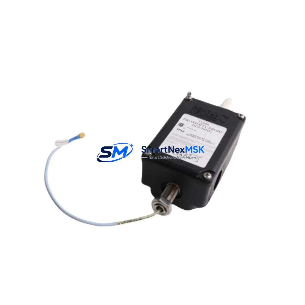
Bently Nevada 31000-28-10-00-235-00-02 Retrofit-Ready Proximity Probe for 31000 Series Control Systems
The Bently Nevada 31000-28-10-00-235-00-02 is a high-precision eddy-current proximity probe engineered for the 31000 Series vibration monitoring platform. As legacy machinery protection systems reach end-of-life or face discontinued spare-parts availability, this probe serves as a verified retrofit solution for plants operating Bently Nevada 3300, 3500, and 7200 Series monitors alongside older 31000 Series front-end hardware. Whether you are replacing a failed sensor on a critical rotating machine or executing a planned control-system upgrade, the 31000-28-10-00-235-00-02 delivers the dimensional accuracy, gap voltage linearity, and cable impedance characteristics required for seamless integration without reprogramming the monitor’s transducer input cards.
Industrial facilities running continuous processes — refineries, power generation plants, compressor stations, and paper mills — cannot afford extended downtime caused by obsolete proximity probe inventory. This unit ships from verified stock, undergoes pre-shipment functional testing against Bently Nevada factory calibration standards, and is backed by a 12-month warranty covering manufacturing defects and performance deviation. Each unit is inspected for tip concentricity, cable continuity, connector integrity, and static sensitivity before dispatch.
Upgrade Compatibility Table
| Parameter | 31000-28-10-00-235-00-02 | Notes |
|---|---|---|
| Probe Series | 31000 Series | Compatible with 3300 XL 8mm driver/extension |
| Tip Diameter | 28 mm | Verify target material: steel or alloy steel preferred |
| Cable Length | 10 ft (approx.) | Match extension cable length to driver range |
| Sensitivity | 200 mV/mil (7.87 V/mm) | Confirm monitor input card sensitivity setting |
| Gap Voltage Range | −10 VDC nominal | Set gap per monitor channel configuration |
| Connector Type | Standard BNC / coaxial | Verify mating connector on junction box or terminal block |
| Monitor Compatibility | 3300, 3500, 7200 Series | Confirm transducer type selection in monitor software |
| Communication | Analog (4–20 mA / voltage) | No protocol migration required for direct replacement |
| Installation | Threaded body, locknut | Torque to spec; use anti-seize on stainless housings |
| Warranty | 12 Months | Covers manufacturing defects and calibration drift |
Retrofit Planning for Existing Automation Systems
Successful integration of the 31000-28-10-00-235-00-02 into an existing machinery protection architecture requires a structured pre-installation review. Begin by auditing the Bently Nevada 3500/42M Proximitor monitor or the 3300 XL driver to confirm that the transducer input configuration matches the probe’s sensitivity curve. If the plant is migrating from an older 3300 Series driver to a 3500 Series rack, the Bently Nevada 3500/20 Power Supply module must be verified for adequate current capacity, as adding proximity channels increases the total draw on the rack’s internal bus.
The extension cable — typically a Bently Nevada 330130 or 330180 Series armored extension — must be selected to complement the probe’s cable length so that the combined probe-plus-extension length falls within the driver’s calibrated range. Mismatched cable lengths are one of the most common causes of gap voltage error and false vibration alarms during commissioning. At the junction box, confirm that the terminal block wiring follows the shield-grounding convention specified in the Bently Nevada TN-13 technical note: shield grounded at the monitor end only, floating at the machine end.
For plants upgrading from a 7200 Series front-end to a 3500 Series rack, the Bently Nevada 3500/92 Communication Gateway may be required to bridge legacy Modbus RTU data to the plant’s DCS or SCADA system. If the existing HMI screens — whether running on a Wonderware InTouch or Rockwell FactoryTalk platform — display vibration trend data from the old monitor, the tag addresses and scaling factors must be updated to reflect the new monitor’s output range before cutover. Failure to update HMI scaling is a frequent source of nuisance trips in the first 24 hours after a monitor swap.
When the control cabinet houses both the Bently Nevada monitor rack and a Rockwell Automation ControlLogix or CompactLogix controller, the I/O mapping between the monitor’s relay outputs and the PLC’s digital input module must be re-verified. The Bently Nevada 3500/32 4-Channel Relay module provides configurable relay logic; confirm that the relay setpoints and time delays are re-entered after any firmware update or module replacement. Similarly, if the plant uses a Bently Nevada 3500/22M Transient Data Interface for startup and coast-down analysis, the interface’s configuration file should be backed up before the retrofit and restored after the new probe is commissioned.
Finally, document the as-found gap voltage for each channel before removing the old probe, and record the as-left gap voltage after installing the 31000-28-10-00-235-00-02. This baseline data is essential for the first scheduled vibration survey and provides evidence of correct installation for the 12-month warranty record.
Downtime Control During System Migration
Minimizing production interruption during a proximity probe replacement begins with pre-staging all replacement components — probe, extension cable, driver, and terminal hardware — at least 48 hours before the planned outage window. For hot-swap scenarios where the machine cannot be fully shut down, coordinate with the control room to place the affected monitor channel in bypass mode using the Bently Nevada 3500 rack’s channel inhibit function. This prevents a spurious trip signal from reaching the PLC or DCS while the probe is being changed.
Before disconnecting the old probe, capture a screenshot or historian export of the current vibration trend from the DCS or from Bently Nevada System 1 software. This snapshot serves as the pre-maintenance baseline and allows the commissioning engineer to confirm that the new probe is reading within the expected range before the channel inhibit is released. If the plant’s safety instrumented system (SIS) is interlocked with the vibration monitor, notify the SIS engineer and follow the management-of-change procedure before bypassing any channel.
After installing the 31000-28-10-00-235-00-02, set the probe gap to the manufacturer’s recommended value (typically −10 VDC ± 0.5 V at the nominal air gap), verify the gap voltage at the monitor front panel or via the 3500 rack’s communication port, and confirm that the vibration reading is stable and consistent with the machine’s known baseline. Release the channel inhibit only after the reading has been stable for a minimum of five minutes at operating speed. Total elapsed time for a well-prepared single-channel probe swap on a 3500 Series rack is typically 45 to 90 minutes, keeping unplanned downtime to an absolute minimum.
Retrofit Support FAQ
Q1: Is the 31000-28-10-00-235-00-02 a direct drop-in replacement for the original 31000 Series probe?
Yes. The 31000-28-10-00-235-00-02 maintains the same tip diameter, thread pitch, sensitivity, and connector standard as the original 31000 Series specification. No modifications to the monitor channel configuration are required for a like-for-like replacement. If you are migrating to a 3500 Series monitor from an older platform, the transducer type selection in the 3500 rack software must be set to match the probe’s sensitivity curve.
Q2: What wiring checks are required before commissioning?
Verify shield grounding (monitor end only), confirm cable polarity at the terminal block, measure the static gap voltage with the machine at rest, and check for continuity between the probe tip and the driver input. Any reading outside the −18 VDC to −2 VDC range at the driver output indicates a wiring fault, incorrect gap, or cable mismatch that must be resolved before the channel is placed in service.
Q3: How is compatibility with the existing HMI and DCS verified?
Compare the monitor’s analog output scaling (mV/mil or V/mm) with the engineering unit conversion configured in the DCS historian tag or HMI faceplate. If the old probe used a different sensitivity, update the DCS scaling factor before cutover. For Bently Nevada System 1 users, re-import the transducer calibration file after the probe swap to ensure that the software’s gap-to-displacement conversion is aligned with the new hardware.
Q4: What does the 12-month warranty cover, and what is the return process?
The 12-month warranty covers manufacturing defects, calibration drift beyond factory tolerance, and connector or cable failures under normal operating conditions. It does not cover damage caused by incorrect installation, over-torquing, chemical exposure, or electrical overstress. To initiate a warranty claim, contact sales@smartnexmsk.com with the purchase order number, installation date, and a description of the observed fault. Replacement units are dispatched within 3 business days of claim approval.
© 2026 SMARTNEXMSK. All rights reserved.
Original Source: https://smartnexmsk.com
Contact: sales@smartnexmsk.com | +86 18259474341


