Bently Nevada 330101-00-12-20-12-CN 3300 XL Retrofit-Ready Proximity Transducer: Compatible Upgrade for Legacy Vibration Monitoring Systems
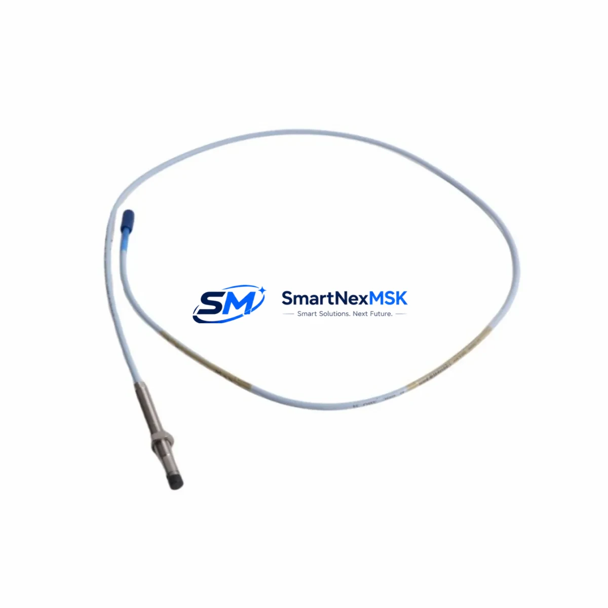
The Bently Nevada 330101-00-12-20-12-CN is an 8mm proximity transducer engineered for the 3300 XL Series continuous vibration monitoring platform. Designed as a direct retrofit replacement for aging or discontinued transducer assemblies, this unit supports smooth migration from legacy Bently Nevada 3300 and 7200 Series installations without requiring changes to existing wiring harnesses, terminal blocks, or monitor rack configurations. Whether you are upgrading a turbine protection system, replacing a failed sensor in a compressor train, or modernizing a control cabinet that has been in service for over a decade, the 330101-00-12-20-12-CN delivers the signal integrity and mechanical compatibility your application demands.
This transducer operates as part of a three-component proximity system, working in conjunction with the 330130 extension cable and the 330180 proximitor sensor to deliver a calibrated output signal to the 3300 XL monitor. When planning a retrofit, engineers must verify that the existing proximitor model matches the transducer gap range and sensitivity specification — typically –200 mV/mil (–7.87 V/mm) for standard 3300 XL assemblies. Mismatched sensitivity curves between the transducer and proximitor will produce erroneous gap voltage readings and may trigger nuisance trips or mask genuine machinery faults.
For installations where the original 330101-00-12-20-12-CN has reached end-of-life or is no longer available through OEM channels, this unit provides a verified drop-in replacement path. The 20-inch (500 mm) armored cable and 12-inch (300 mm) integral cable configuration match the original dimensional envelope, eliminating the need to re-route conduit or modify junction box penetrations. Terminal connections at the field junction box follow the standard Bently Nevada color-coded wiring convention, allowing technicians to complete the swap using existing documentation without re-engineering the loop.
Upgrade Compatibility Table
| Parameter | Specification / Compatibility Detail |
|---|---|
| SKU / Part Number | 330101-00-12-20-12-CN |
| Transducer Diameter | 8 mm |
| Integral Cable Length | 12 inches (300 mm) |
| Extension Cable Compatibility | 330130 Series (5 m, 9 m standard lengths) |
| Proximitor Compatibility | 330180, 330185 (3300 XL Series) |
| Monitor Rack Compatibility | 3300 XL 8-slot, 3300 XL 16-slot monitor racks |
| Output Sensitivity | –200 mV/mil (–7.87 V/mm) |
| Supply Voltage | –24 VDC (from proximitor) |
| Linear Range | 10–90 mil (0.25–2.29 mm) |
| Installation Interface | M10 × 1 threaded body, standard bracket mount |
| Communication / Signal Protocol | Analog DC voltage (–24 V loop), compatible with 3300 XL monitor I/O |
| Replacement Recommendation | Direct drop-in for 330101-00-12-20-12-CN; verify proximitor model before installation |
| Commissioning Requirement | Gap voltage verification at 50 mil nominal; OK LED confirmation on proximitor |
| Warranty | 12-Month Warranty — covers manufacturing defects and signal calibration |
Retrofit Planning for Existing Automation Systems
A successful retrofit of the 330101-00-12-20-12-CN into an operating plant begins well before the maintenance window opens. The first step is a full audit of the existing proximity system loop: confirm the proximitor model (typically a 330180 or 330185 mounted in the field junction box), inspect the 330130 extension cable for jacket damage or connector corrosion, and verify that the monitor channel in the 3300 XL rack is configured for the correct transducer type and gap range. If the monitor is a 3300/16 or 3300/20 card, check the DIP switch settings for channel sensitivity — an incorrect switch position will cause the channel to report a false OK status even when the transducer gap is out of range.
Power supply capacity is a critical checkpoint. The 3300 XL system draws –24 VDC from a dedicated power supply module, and adding replacement transducers to an already-loaded rack can push the supply toward its rated output current. Review the power budget for the full rack before the swap, particularly if the cabinet also houses a 3500/22M transient data interface or a 3500/42M proximitor I/O module from the newer 3500 Series platform. If the existing power supply is marginal, plan to install a supplementary power supply module before the transducer replacement to avoid a supply-induced trip during commissioning.
Wiring adaptation is straightforward for like-for-like replacements. The 330101-00-12-20-12-CN uses the same three-conductor shielded cable convention as its predecessors: the shield drain wire connects to the junction box ground lug, the center conductor carries the –24 V supply from the proximitor, and the outer conductor returns the gap voltage signal. If the existing terminal block is a Phoenix Contact or Weidmüller DIN-rail type, no re-termination is required — simply loosen the existing screw terminals, extract the old cable conductors, and insert the new ones. For installations using Bently Nevada’s own field junction box (model 02701179), the terminal layout is printed on the inside of the cover, eliminating the need to reference external drawings during the swap.
Module address and channel assignment in the 3300 XL rack do not change during a transducer replacement, since the monitor card identifies channels by physical slot position rather than by transducer serial number. However, if the retrofit is part of a broader migration from a 3300 Series rack to a 3500 Series rack — for example, replacing a 3300/16 monitor with a 3500/40M proximitor monitor — the channel configuration must be re-entered in System 1 or the 3500 Rack Configuration Software. In this scenario, the 330101-00-12-20-12-CN transducer remains compatible, but the proximitor changes to a 3500/40 field unit, and the extension cable routing may need to be adjusted to reach the new field junction box location.
HMI screen updates are often overlooked during transducer retrofits. If the plant DCS or SCADA system displays vibration trend data sourced from the 3300 XL monitor via a 3300/46M communication gateway or a Modbus TCP interface, verify that the tag names and engineering unit scaling in the HMI database still match the new channel configuration after the swap. A mismatch between the monitor’s output scaling and the HMI’s input range can cause the vibration trend to display incorrect amplitude values without triggering any alarm — a silent failure mode that is difficult to detect during a short commissioning window.
Downtime Control During System Migration
Minimizing unplanned downtime during a proximity transducer replacement requires a structured pre-outage preparation protocol. Before the maintenance window, prepare a complete spare kit that includes the 330101-00-12-20-12-CN transducer, a matched 330130 extension cable, a spare 330180 proximitor, and a calibrated gap-setting tool. Having all components staged at the work site eliminates the most common cause of extended outages: waiting for a missing part to arrive from the storeroom.
Protect the original program logic and alarm setpoints by exporting the full rack configuration from the 3300 XL monitor before the outage begins. Use the Bently Nevada System 1 software to save a configuration snapshot that includes all channel setpoints, alert and danger thresholds, time-delay settings, and OK relay logic. This snapshot serves as both a restoration baseline and a commissioning checklist — after the new transducer is installed and gapped, compare the live channel readings against the saved configuration to confirm that all parameters are within tolerance before returning the machine to service.
For critical machinery where even a brief loss of vibration monitoring is unacceptable, consider a hot-swap strategy using a bypass relay module to hold the OK relay in the energized state during the transducer exchange. This approach maintains the control system’s permissive logic in the run state while the transducer is disconnected, preventing a spurious trip that would shut down the machine train. Document the bypass activation and deactivation times in the maintenance record, and confirm that the bypass is removed and the channel is restored to normal monitoring mode before the machine is returned to full load.
After installation, perform a systematic commissioning sequence: apply power to the proximitor, measure the gap voltage at the monitor channel input terminals, adjust the transducer gap to achieve the nominal –10.0 VDC output at 50 mil, and confirm that the OK LED on the proximitor is illuminated. Record the as-left gap voltage in the maintenance log for future reference. If the monitor channel is connected to a 3300/46M Modbus gateway or a 4–20 mA output module, verify that the analog output is tracking the gap voltage correctly before releasing the channel to the DCS.
Retrofit Support FAQ
Q1: Is the 330101-00-12-20-12-CN a direct replacement for the original Bently Nevada part, and will it work with my existing 330180 proximitor?
Yes. The 330101-00-12-20-12-CN is a verified drop-in replacement for the original Bently Nevada part of the same number. It is fully compatible with the 330180 and 330185 proximitor models used in 3300 XL Series installations. No recalibration of the proximitor is required provided the existing proximitor is in good condition and the gap is set correctly during installation.
Q2: What wiring changes are needed when replacing the transducer in an existing field junction box?
For a like-for-like replacement, no wiring changes are required. The 330101-00-12-20-12-CN uses the same three-conductor shielded cable and the same terminal assignment as the original unit. Simply transfer the existing conductors to the new transducer’s cable ends using the same terminal positions. If the junction box uses a Bently Nevada 02701179 field junction box, the terminal layout printed on the cover lid provides all the guidance needed for correct re-termination.
Q3: How do I verify compatibility before installation, and what commissioning checks are required?
Before installation, confirm that the proximitor model is 330180 or 330185, that the extension cable is a 330130 Series unit in good condition, and that the monitor channel is configured for an 8mm transducer with standard –200 mV/mil sensitivity. After installation, set the transducer gap to achieve –10.0 VDC ±0.5 VDC at the monitor channel input, confirm the OK LED on the proximitor, and verify that the monitor channel is not in an alert or danger state before returning the machine to service.
Q4: What does the 12-month warranty cover, and how is the unit tested before shipment?
Every 330101-00-12-20-12-CN unit is tested for output sensitivity, linear range, and cable continuity before shipment. The 12-month warranty covers manufacturing defects, signal calibration drift beyond specification, and cable assembly failures under normal operating conditions. Units that fail in service within the warranty period are replaced or repaired at no charge. Contact our technical support team with the unit serial number and a description of the failure mode to initiate a warranty claim.
© 2026 SMARTNEXMSK. All rights reserved.
Original Source: https://smartnexmsk.com
Contact: sales@smartnexmsk.com | +86 18259474341


