Bently Nevada 330101-00-13-15-02-CN 3300 XL Retrofit-Ready Proximity Probe: Compatible Modernization and Legacy System Upgrade
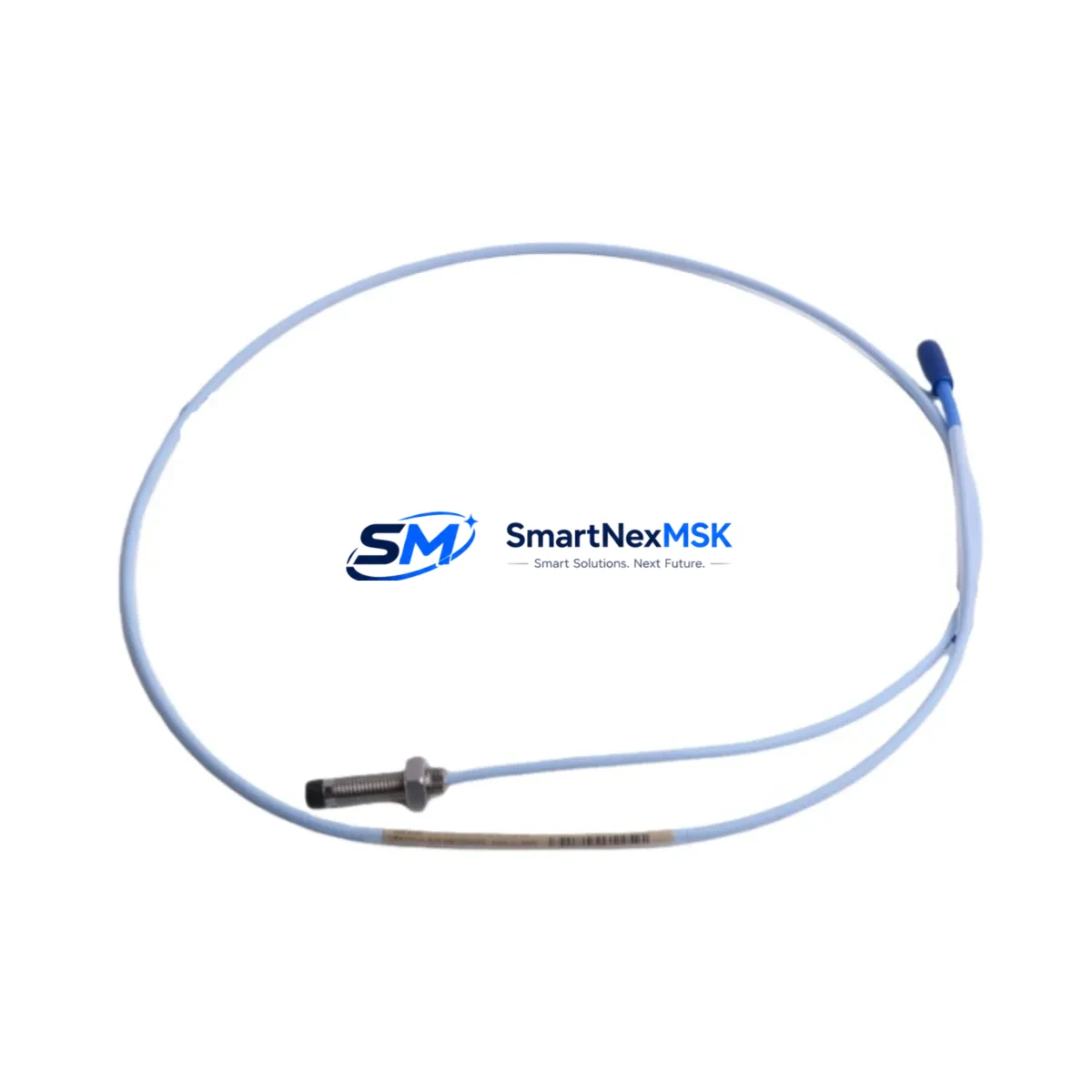
The Bently Nevada 330101-00-13-15-02-CN is an 8mm eddy-current proximity probe engineered for the 3300 XL Series vibration monitoring platform. As legacy rotating machinery protection systems approach end-of-life or face discontinued spare parts availability, this probe serves as a direct retrofit replacement for aging 3300 Series and early 3300 XL installations. Whether you are upgrading a turbine protection panel, replacing a failed proximity sensor on a compressor train, or modernizing a control cabinet that has been in continuous service for over a decade, the 330101-00-13-15-02-CN provides a verified drop-in solution with minimal re-engineering.
This probe is designed to interface directly with the 3300 XL proximitor/seismic monitor, maintaining the standard 5-metre probe-to-proximitor cable length and the -24 VDC bias voltage characteristic of the 3300 XL measurement chain. The 8mm tip diameter and the integrated 330130-080-00-00 extension cable connector ensure backward compatibility with existing conduit runs, terminal blocks, and junction boxes already installed in the field.
Upgrade Compatibility Table
| Parameter | 330101-00-13-15-02-CN (This Unit) | Legacy 3300 Series Probe | Retrofit Notes |
|---|---|---|---|
| Probe Tip Diameter | 8 mm | 8 mm | Direct fit; no bracket modification required |
| Cable Length | 5 m (standard) | 5 m | Verify extension cable part number before ordering |
| Bias Voltage | -24 VDC nominal | -24 VDC | Compatible with 3300 XL proximitor output |
| Frequency Range | DC – 10,000 Hz | DC – 10,000 Hz | No signal conditioning change needed |
| Target Material | Steel / Inconel | Steel / Inconel | Confirm shaft material; use calibration factor if non-standard |
| Connector Type | Standard BNC / integral | Standard BNC | Matches existing junction box wiring |
| Monitor Compatibility | 3300 XL Monitor (3300/16, 3300/20, 3300/25) | 3300 Series Monitor | Confirm monitor firmware version for XL compatibility |
| Installation Standard | API 670 5th Edition | API 670 4th Edition | Review gap voltage specification during commissioning |
| Commissioning Check | Gap voltage: -10.0 VDC ±0.5 V | -10.0 VDC ±0.5 V | Adjust probe tip-to-shaft gap to 1.0 mm nominal |
| Warranty | 12 Months | N/A (legacy) | Covered from date of shipment |
Retrofit Planning for Existing Automation Systems
Successful integration of the 330101-00-13-15-02-CN into an existing machinery protection system requires a structured pre-installation review. Begin by auditing the current 3300 XL monitor rack configuration. Most installations pair this probe with a 3300/16-02-01-00 dual-channel monitor card seated in a 3300 Series rack. Confirm that the rack backplane is a standard 19-inch DIN-rail or panel-mount chassis and that the monitor card firmware supports the 8mm probe sensitivity scale factor of 7.87 V/mm.
Terminal wiring should be verified against the original loop drawing. The probe cable shield must be grounded at one end only — typically at the proximitor housing — to prevent ground loops that introduce noise into the vibration signal. If the existing 330130-080-00-00 extension cable shows insulation degradation or connector corrosion, replace it simultaneously with the probe to avoid introducing a new fault source into a repaired measurement chain.
For installations where the original 3300 Series proximitor (such as the 330180-91-00 or 330180-X1-05) has been replaced by a 3300 XL proximitor/seismic monitor, verify that the new monitor’s OK relay output is correctly wired to the plant DCS or safety instrumented system. Many older control cabinets route the OK relay through a 3500/22M transient data interface or a legacy 3500 Series rack, and the relay logic may need to be re-mapped in the DCS configuration if the monitor card slot address has changed.
Power supply capacity is a critical check point. The 3300 XL monitor rack typically draws from a dedicated -24 VDC instrument power supply. If the control cabinet power budget is already near capacity due to added I/O modules or communication gateways, calculate the additional current draw before commissioning. A 3300/16 dual-channel monitor card draws approximately 150 mA; adding two probes and their proximitors increases the load by roughly 60 mA per channel pair.
For plants migrating from a standalone 3300 Series panel to an integrated 3500 Series machinery protection system, the 330101-00-13-15-02-CN probe remains compatible as an input sensor. The 3500/42M four-channel monitor accepts the same probe-and-proximitor signal chain, and the Bently Nevada System 1 software platform can trend and alarm on the same vibration and position data without requiring re-calibration of the probe itself. If the migration path includes a 3500/22M transient data interface, ensure the Modbus or OPC-DA communication link to the plant historian is re-established after the rack swap.
HMI screen updates are often overlooked during probe replacements. If the plant uses a Wonderware InTouch or Ignition SCADA display that references the old monitor card tag names, update the tag database to reflect any new rack slot addresses or monitor card serial numbers. This prevents false alarm conditions during the first hours of post-retrofit operation.
Downtime Control During System Migration
Minimizing unplanned downtime during a proximity probe retrofit requires a parallel preparation strategy. Before taking the machine offline, pre-configure the replacement 330101-00-13-15-02-CN probe assembly on the bench: verify the gap voltage in a test fixture, confirm the cable continuity, and document the as-found bias voltage reading from the existing probe. This baseline allows the commissioning engineer to compare the new probe’s output directly against the historical trend data stored in the System 1 historian or the plant DCS.
Where process conditions allow, perform a hot-standby swap using a spare monitor channel if the 3300 XL rack has an unused slot. Route the new probe signal to the spare channel, verify the output, and then switch the alarm logic to the new channel before removing the old probe. This approach keeps the machine in a monitored state throughout the replacement and avoids a full protection bypass.
For critical turbine or compressor trains where a full bypass is unavoidable, coordinate with the operations team to schedule the outage during a planned maintenance window. Prepare a written bypass authorization, notify the safety instrumented system engineer, and ensure the 3500 Series or 3300 XL rack’s OK relay is inhibited in the DCS before disconnecting the probe cable. Restore the OK relay and verify alarm setpoints immediately after the new probe is gapped and the bias voltage is confirmed within specification.
Program logic preservation is straightforward for this probe type since the 330101-00-13-15-02-CN is a passive sensor — it does not store configuration data. However, if the associated proximitor or monitor card is also being replaced, export the monitor configuration from Bently Nevada’s System 1 software or the 3500 Rack Configuration Utility before the outage. Re-import the configuration file after the new hardware is installed to restore alarm setpoints, danger levels, and transducer OK limits without manual re-entry.
Retrofit Support FAQ
Q1: Is the 330101-00-13-15-02-CN a direct replacement for the earlier 330101-00-13-10-02-CN probe?
A: Yes. The primary difference is the cable length suffix. The -15- designation indicates a 5-metre probe cable, while -10- indicates a shorter run. Verify your existing conduit length before substituting. If the original cable was routed with excess coiled at the junction box, the 5-metre version is a direct fit in most installations.
Q2: What gap voltage should I set during commissioning?
A: The nominal gap voltage for an 8mm probe on a steel shaft is -10.0 VDC ±0.5 V, corresponding to a physical gap of approximately 1.0 mm. Measure the bias voltage at the proximitor output terminals using a calibrated digital multimeter before energizing the monitor card. Document the as-left gap voltage in the maintenance record for future reference.
Q3: Will this probe work with a 3500/42M monitor card in a 3500 Series rack?
A: Yes, provided the 3500/42M is configured for the 8mm probe sensitivity scale factor (7.87 V/mm). The probe-and-proximitor signal chain is identical between the 3300 XL and 3500 Series platforms. No hardware modification is required; only the monitor card configuration in the 3500 Rack Configuration Utility needs to confirm the correct transducer type selection.
Q4: What does the 12-month warranty cover?
A: The 12-month warranty covers manufacturing defects in materials and workmanship from the date of shipment. Each unit undergoes pre-shipment functional testing including bias voltage verification, cable continuity check, and connector integrity inspection. Warranty claims are processed through SMARTNEXMSK’s technical support team with a typical response time of 1–2 business days.
© 2026 SMARTNEXMSK. All rights reserved.
Original Source: https://smartnexmsk.com
Contact: sales@smartnexmsk.com | +86 18259474341


