Bently Nevada 330101-00-18-20-12-05 Retrofit-Ready Proximity Transducer for 3300 XL Control Systems
The Bently Nevada 330101-00-18-20-12-05 is an 8mm eddy-current proximity transducer engineered for seamless integration into existing 3300 XL continuous monitoring systems. As legacy vibration monitoring infrastructure ages across rotating machinery platforms — turbines, compressors, pumps, and gearboxes — the demand for verified drop-in replacements that preserve original signal chain integrity has never been higher. This transducer is stocked, tested, and ready to ship as a direct retrofit solution for facilities managing end-of-life spares or executing planned system upgrades.
Upgrade Compatibility Table
| Parameter | Detail |
|---|---|
| SKU / Part Number | 330101-00-18-20-12-05 |
| Series Compatibility | Bently Nevada 3300 XL Monitoring System |
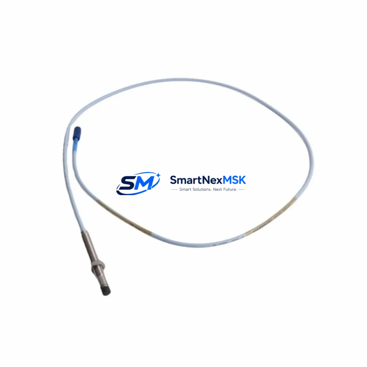
| Transducer Type | 8mm Eddy-Current Proximity Transducer |
| Cable Length | 5m (integral cable) |
| Extension Cable Compatibility | 3300 XL Extension Cable (330130 series) |
| Driver / Proximitor Compatibility | 3300 XL Proximitor Sensor (330180 series) |
| Connector Type | Standard BNC / coaxial per 3300 XL spec |
| Installation Requirement | Direct mount; verify gap voltage per OEM spec (typically −10 VDC at nominal gap) |
| Communication / Signal | Analog voltage output; compatible with 3500 series rack I/O and legacy 3300 monitors |
| Replacement Recommendation | Verified drop-in for 330101-00-18-20-12-05; confirm Proximitor model before installation |
| Commissioning Note | Re-gap and re-calibrate after installation; verify OK/NOT OK relay thresholds in monitor |
| Warranty | 12-Month Warranty — covers manufacturing defects and signal performance |
Retrofit Planning for Existing Automation Systems
Retrofitting a 3300 XL proximity transducer system requires a structured approach that accounts for the full signal chain — from the probe tip to the monitor rack output. The 330101-00-18-20-12-05 transducer is the field-mounted sensing element; its performance depends on correct pairing with the 330130 series extension cable and the 330180 series Proximitor sensor. When planning a retrofit, engineers should first audit the existing cable routing and conduit fill to confirm that the replacement cable assembly can be pulled without disturbing adjacent wiring.
Power supply integrity is a critical pre-check. The 3300 XL Proximitor requires a stable −24 VDC supply, typically sourced from a dedicated instrument power module within the control cabinet. If the existing power module is aging or undersized, it is advisable to replace it concurrently — a failing supply will cause erratic gap voltage readings that mimic transducer failure. Similarly, the 3500/22M Transient Data Interface or the 3500/42M Proximitor I/O Module in the rack should be inspected for firmware currency and channel configuration before the new transducer is commissioned.
For facilities running a mixed fleet of 3300 and 3500 series monitors, the signal output of the 330101-00-18-20-12-05 is compatible with both platforms, provided the Proximitor model is matched correctly. The 3500 series rack accepts the same analog voltage signal and can be configured via the 3500 Rack Configuration Software to recognize the new transducer’s sensitivity factor (typically 7.87 V/mm). If the plant historian or DCS — such as a Honeywell Experion or Emerson DeltaV node — is receiving vibration data from the 3500 rack via Modbus or OPC-DA, no protocol reconfiguration is required after a like-for-like transducer swap.
I/O mapping should be verified in the monitor’s configuration before the machine is returned to service. Channel tags, engineering unit scaling, and alarm setpoints stored in the 3500 rack are transducer-agnostic and will carry over without modification. However, if the retrofit is part of a broader migration from a 3300 monitor to a 3500/40M Proximitor Monitor, the channel configuration must be rebuilt in the new rack and validated against the original alarm philosophy document. HMI graphics on the operator workstation — whether running System 1 Evolution or a third-party SCADA — should be checked to confirm that the vibration trend tags are populating correctly after the swap.
Backplane and rack slot assignments are another area requiring attention during multi-channel retrofits. If multiple transducers are being replaced simultaneously across a 3500 rack, each slot’s I/O module address must be confirmed against the loop diagram before power-up. The 3500/20 Rack Interface Module manages communication between the rack and the host system; its configuration should be backed up before any hardware changes are made.
Downtime Control During System Migration
Minimizing unplanned downtime during a proximity transducer replacement begins with pre-staging all replacement components — transducer, extension cable, Proximitor, and any required mounting hardware — before the maintenance window opens. The 330101-00-18-20-12-05 ships pre-tested and gap-verified, which eliminates the most time-consuming step in field commissioning. A typical like-for-like swap on a single channel can be completed in under two hours when the replacement assembly is pre-staged and the gap setting procedure is rehearsed.
To protect original program logic during the migration, the 3500 rack configuration file should be exported and archived using the 3500 Rack Configuration Software before any hardware is disturbed. This file captures all channel configurations, alarm setpoints, relay logic, and communication parameters. If the rack must be powered down for the swap, the configuration can be reloaded in minutes after power restoration, eliminating the risk of parameter loss.
For critical machinery that cannot tolerate a full shutdown, a bypass relay or a temporary hardwired jumper on the NOT OK output can maintain control continuity while the transducer is being replaced. This approach must be coordinated with the control room operator and documented in the permit-to-work system. Once the new transducer is installed and gapped, the bypass is removed, the channel is enabled, and the vibration trend is monitored for at least one full machine start-stop cycle before the work order is closed.
All replacement units supplied by SMARTNEXMSK are covered by a 12-month warranty and undergo outgoing inspection prior to shipment, including gap voltage verification and insulation resistance testing. This ensures that the replacement transducer performs to specification from the first power-up, reducing the risk of a repeat outage caused by a defective spare.
Retrofit Support FAQ
Q1: Is the 330101-00-18-20-12-05 a direct replacement for the original Bently Nevada part?
Yes. This unit is a verified drop-in replacement for the original 330101-00-18-20-12-05 proximity transducer. It maintains the same 8mm tip diameter, integral cable length, sensitivity factor, and connector specification as the OEM part. No mechanical or electrical modifications are required for a like-for-like swap within the 3300 XL system.
Q2: What commissioning steps are required after installation?
After mechanical installation, the air gap between the transducer tip and the shaft must be set to the value specified in the machine’s loop diagram (typically 1.0–1.5 mm, corresponding to approximately −10 VDC output). The gap voltage should be measured at the Proximitor output terminals using a calibrated multimeter. Once the gap is confirmed, the monitor’s OK/NOT OK relay thresholds should be verified and the vibration trend should be observed through at least one machine start cycle before the channel is returned to automatic protection.
Q3: Can this transducer be used with a 3500 series monitor rack?
Yes, provided the correct Proximitor model (330180 series) is used. The analog voltage output of the 330101-00-18-20-12-05 is fully compatible with the 3500/40M Proximitor Monitor and the 3500/42M Proximitor I/O Module. The sensitivity factor (7.87 V/mm) must be entered correctly in the 3500 rack channel configuration to ensure accurate engineering unit scaling.
Q4: What does the 12-month warranty cover?
The 12-month warranty covers manufacturing defects, signal performance deviations from published specifications, and connector integrity. Each unit undergoes outgoing inspection including gap voltage verification and insulation resistance testing before shipment. Warranty claims are processed directly through SMARTNEXMSK; contact sales@smartnexmsk.com with the order number and a description of the fault.
© 2026 SMARTNEXMSK. All rights reserved.
Original Source: https://smartnexmsk.com
Contact: sales@smartnexmsk.com | +86 18259474341


