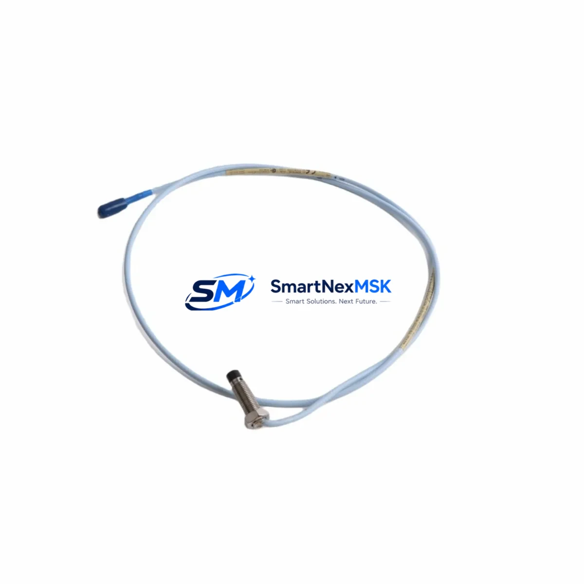
Bently Nevada 330101-00-20-05-02-00 Retrofit-Ready Proximity Transducer for 3300 XL Control Systems
When aging vibration monitoring infrastructure demands a reliable upgrade path, the Bently Nevada 330101-00-20-05-02-00 8mm proximity transducer stands as the definitive retrofit solution for 3300 XL series control systems. Engineered to deliver seamless compatibility with existing Bently Nevada architectures, this transducer enables maintenance engineers and reliability teams to execute controlled system modernization without compromising measurement integrity or production continuity. Whether you are replacing a worn sensor in a critical turbine protection loop or upgrading an entire vibration monitoring rack, the 330101-00-20-05-02-00 provides the dimensional, electrical, and signal compatibility required for a confident, low-risk retrofit.
The 330101-00-20-05-02-00 is a direct-fit replacement for legacy 3300 series proximity transducers, sharing the same 8mm tip diameter, standard 5-metre extension cable interface, and –24 VDC bias voltage operating range. Its output sensitivity of 7.87 V/mm (200 mV/mil) is fully compatible with the signal conditioning expectations of the 3300 XL Proximitor® sensor, the 3500/42M Proximitor®/Seismic Monitor, and the 3500/40M Proximitor® Monitor. This means that when installed as a drop-in replacement, no recalibration of monitor gap voltage setpoints is required, provided the original installation gap of approximately 1.0 mm (40 mil) is maintained during commissioning.
Upgrade Compatibility Table
| Parameter | Specification / Retrofit Note |
|---|---|
| SKU / Part Number | 330101-00-20-05-02-00 |
| Series | Bently Nevada 3300 XL |
| Tip Diameter | 8 mm |
| Cable Length | 5 m (extension cable) |
| Output Sensitivity | 7.87 V/mm (200 mV/mil) |
| Bias Voltage | –24 VDC nominal |
| Operating Temperature | –35°C to +120°C |
| Connector Interface | Standard 3300 XL coaxial, compatible with 330130 extension cable |
| Monitor Compatibility | 3500/40M, 3500/42M, 3300 XL Proximitor® |
| Communication / Signal | Analog voltage output; no protocol migration required |
| Installation Gap | ~1.0 mm (40 mil) recommended |
| Replacement Scope | Direct drop-in for 330101 series; no wiring modification needed |
| Commissioning Requirement | Verify gap voltage at monitor front panel; confirm OK relay status |
| Warranty | 12-Month Warranty — covers manufacturing defects and signal performance |
Retrofit Planning for Existing Automation Systems
A successful retrofit of the 330101-00-20-05-02-00 begins well before the sensor is physically installed. The first step is a thorough audit of the existing vibration monitoring rack. In most 3300 XL installations, the rack will house a combination of the 3300 XL Proximitor® sensor, the 3500 rack power supply (typically the 3500/15 Power Supply module), and one or more 3500/42M Proximitor®/Seismic Monitor cards. Before removing the legacy transducer, engineers should document the current gap voltage reading displayed on the 3500/42M front panel — this baseline value is critical for post-installation verification.
The 330130-020-00-00 extension cable, which connects the transducer to the Proximitor® sensor, should be inspected for continuity and connector integrity. In many retrofit scenarios, the extension cable is replaced simultaneously with the transducer to eliminate a common source of intermittent signal faults. The coaxial connector at the Proximitor® input should be cleaned and inspected for corrosion, particularly in installations exposed to high humidity or chemical vapors.
For installations where the 3500/42M monitor is also being upgraded to a 3500/42M-01 or newer firmware revision, engineers must verify that the channel configuration stored in the 3500 Rack Configuration Software (RCS) correctly reflects the transducer sensitivity and gap voltage parameters for the 330101-00-20-05-02-00. The RCS configuration file should be backed up before any hardware change is made. If the plant uses a System 1 Evolution condition monitoring platform to aggregate vibration data from multiple 3500 racks, the channel tag assignments and alarm setpoints should be reviewed in the System 1 database to ensure continuity after the swap.
In turbine control cabinets where the 3500 rack interfaces with a DCS or safety system via a 3500/92 Communication Gateway, the Modbus or OPC-DA data map should be verified to confirm that the channel address for the replaced transducer remains unchanged. This is particularly important in plants where the DCS historian — such as an Emerson DeltaV historian or an OSIsoft PI data archive — is configured to trend gap voltage and vibration amplitude from specific Modbus register addresses. An unverified address shift can result in silent data loss that goes undetected until the next scheduled audit.
Where the existing installation uses a 3300 XL Proximitor® sensor rather than the newer 3500-series monitor, the retrofit path is equally straightforward. The 330101-00-20-05-02-00 is electrically and mechanically identical to the original 330101 transducer family, so no changes to the Proximitor® sensor wiring terminal block or the field junction box are required. The field technician need only confirm the correct installation gap using a digital multimeter measuring the DC bias voltage at the Proximitor® output terminals, then secure the transducer locknut and restore the machine to service.
Downtime Control During System Migration
Minimizing unplanned downtime during a proximity transducer retrofit requires a disciplined pre-outage preparation process. The 330101-00-20-05-02-00 should be bench-tested prior to the maintenance window using a calibrated target material (typically AISI 4140 steel) to verify output sensitivity and linearity across the full measurement range. This pre-verification step eliminates the risk of discovering a defective replacement unit after the machine has already been taken offline.
During the outage window, the recommended sequence is: (1) place the 3500/42M monitor channel in bypass mode to suppress spurious alarms during the transducer swap; (2) remove the legacy transducer and extension cable assembly; (3) install the 330101-00-20-05-02-00 with the replacement 330130 extension cable; (4) adjust the installation gap to achieve a bias voltage of approximately –10.0 VDC at the Proximitor® output; (5) release the monitor channel from bypass and confirm the OK relay energizes; (6) verify that the vibration amplitude reading is within the expected baseline range for the machine at rest.
For plants operating under a safety instrumented system (SIS) framework where the vibration channel feeds a safety PLC or a dedicated safety monitor such as the 3500/33 16-Channel Relay Module, the bypass and restoration sequence must be coordinated with the SIS engineer to ensure that the safety function is not inadvertently defeated during the swap. All bypass actions should be documented in the plant’s management of change (MOC) system and signed off by the responsible engineer before work begins.
By following this structured approach, most 330101-00-20-05-02-00 retrofit installations can be completed within a two-hour planned maintenance window, preserving the original program logic, alarm setpoints, and historian data continuity without requiring any changes to the control system software or HMI graphics. All units are shipped with an individual test report confirming bias voltage, sensitivity, and linearity, supporting rapid commissioning and audit traceability. Stock is maintained for immediate dispatch, and all units are covered by a 12-month warranty from the date of shipment.
Retrofit Support FAQ
Q1: Is the 330101-00-20-05-02-00 a direct drop-in replacement for my existing 330101 series transducer?
Yes. The 330101-00-20-05-02-00 is dimensionally and electrically compatible with all 330101 series proximity transducers used in 3300 XL and 3500-series vibration monitoring systems. No wiring modifications or monitor reconfiguration are required, provided the installation gap is set correctly during commissioning.
Q2: What commissioning checks are required after installation?
After installation, verify the DC bias voltage at the Proximitor® output terminals (target: approximately –10.0 VDC at 1.0 mm gap), confirm the OK relay on the 3500/42M monitor is energized, and check that the vibration amplitude reading is consistent with the machine’s known baseline. If the system uses a 3500/92 Communication Gateway, verify that the Modbus data map is returning valid values for the replaced channel.
Q3: Does the unit come with a test report, and what does the 12-month warranty cover?
Yes. Every 330101-00-20-05-02-00 unit is shipped with an individual outgoing test report documenting bias voltage, output sensitivity, and linearity verification. The 12-month warranty covers manufacturing defects and signal performance failures under normal operating conditions. Units that fail within the warranty period are replaced or refunded without additional cost.
Q4: Can you support long-term supply for multi-unit retrofit projects or ongoing spare parts programs?
Yes. SMARTNEXMSK maintains dedicated inventory of the 330101-00-20-05-02-00 and related 3300 XL / 3500-series components to support both immediate replacement needs and planned retrofit programs. For multi-unit orders or scheduled maintenance contracts, please contact our team to discuss lead times, pricing, and consignment stock arrangements.
© 2026 SMARTNEXMSK. All rights reserved.
Original Source: https://smartnexmsk.com
Contact: sales@smartnexmsk.com | +86 18259474341


