Bently Nevada 330101-00-20-50-02-CN Spare 3300 XL: Precision Spare for Vibration Monitoring Continuity
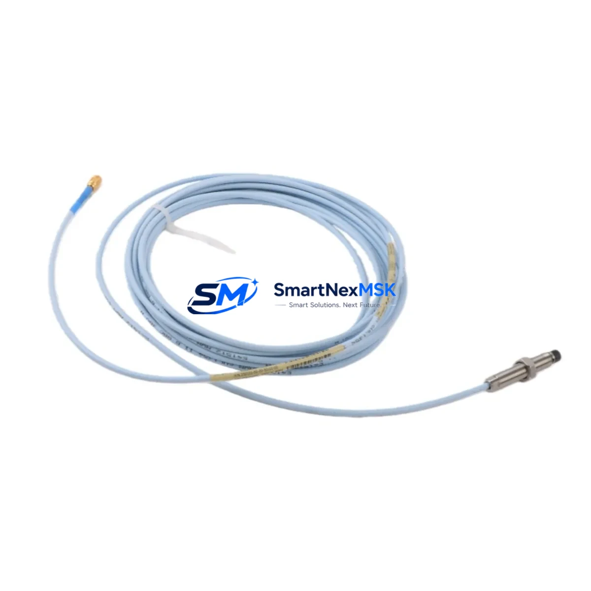
The Bently Nevada 330101-00-20-50-02-CN is an 8mm eddy current proximity probe engineered for the 3300 XL Series continuous vibration monitoring platform. In rotating machinery protection systems — turbines, compressors, pumps, and gearboxes — this probe is a front-line sensing element responsible for shaft displacement, radial vibration, and thrust position measurement. When this component degrades or fails, the entire protection loop is compromised, exposing critical assets to undetected mechanical faults and unplanned downtime.
Sourced as an original spare, the 330101-00-20-50-02-CN is stocked and tested prior to shipment, ensuring that maintenance teams can execute rapid field replacement without extended lead times. Each unit ships with a 12-month warranty covering manufacturing defects and functional performance under rated operating conditions.
Spare Maintenance Table
| Parameter | Specification |
|---|---|
| SKU / Part Number | 330101-00-20-50-02-CN |
| Brand | Bently Nevada |
| Series | 3300 XL |
| Probe Diameter | 8 mm |
| Cable Length | 2.0 m (integral cable) |
| Extension Cable | 330130 Series (5 m / 9 m options) |
| Compatible Driver | 3300 XL 8mm Proximitor® Sensor (330180 Series) |
| Sensitivity | 7.87 V/mm (200 mV/mil) |
| Linear Range | 0.25 – 2.26 mm (10 – 89 mil) |
| Supply Voltage | -24 VDC (nominal) |
| Operating Temperature | -35°C to +177°C |
| Connector Type | CN (Chinese standard connector) |
| Application | Radial vibration, axial thrust, differential expansion |
| Compatibility | 3300 XL monitoring racks, 3500 Series (with adapter), TDXnet systems |
| Condition | Original, new-in-box or tested surplus |
| Warranty | 12 Months — covers manufacturing defects and functional performance |
| Lead Time | In stock — ships within 1–3 business days |
Maintenance Planning for Continuous Operation
Replacing the 330101-00-20-50-02-CN in the field is rarely an isolated task. Maintenance engineers performing a planned or emergency swap of this proximity probe should treat the replacement as an opportunity to audit the full vibration monitoring loop. The probe operates as part of a three-component system: the probe itself, the extension cable (typically a 330130-045-00-00 or equivalent 5 m extension), and the Proximitor® driver module (330180-X1-05). If the probe has failed due to cable damage, contamination, or mechanical impact, the extension cable and driver should be inspected and functionally tested before the new probe is commissioned.
Within the 3300 XL monitoring rack, the associated I/O module and signal conditioning card should be verified for correct gap voltage output — typically between -10 VDC and -18 VDC at the nominal air gap. If gap voltage is outside this range after probe replacement, the issue may lie in the 3300 XL rack power supply module or the backplane termination board rather than the probe itself. Maintenance teams should also check the -24 VDC power supply rail feeding the Proximitor® sensor, as voltage sag or ripple can cause false vibration readings even with a new probe installed.
For facilities running 3500 Series machinery protection systems alongside legacy 3300 XL installations, it is advisable to maintain cross-compatible spares. The 3500/42M position monitor and 3500/40M proximitor I/O module accept 8mm probes from the same family, reducing the number of unique SKUs required in the spare parts cabinet. Similarly, the 330105-02-12-10-02-CN (5 mm variant) and 330103-00-20-50-02-CN (standard CN connector, 20 mil range) are frequently stocked alongside the 330101 series to cover mixed-probe installations on the same machine train.
During control cabinet inspections, technicians should also verify the integrity of terminal blocks connecting probe cables to the monitoring rack — loose or corroded terminals are a common source of intermittent vibration alarms that are misdiagnosed as probe failure. Relay output modules within the 3300 XL rack, responsible for trip and alarm actuation, should be tested for correct setpoint response after any probe replacement to confirm the protection loop is fully functional end-to-end.
For older systems approaching end-of-support, stocking a minimum of two 330101-00-20-50-02-CN probes per machine train is a recognized best practice in rotating equipment maintenance programs. This buffer supports both planned annual turnarounds and unplanned emergency replacements without waiting on international procurement cycles.
Site Replacement Workflow
Step 1 — Isolation and Lockout: Follow site LOTO procedures. De-energize the Proximitor® driver by removing the -24 VDC supply at the rack terminal or field junction box. Do not disconnect the probe cable under live voltage.
Step 2 — Gap Measurement and Documentation: Before removing the old probe, record the installed air gap (typically 1.0–1.5 mm for most shaft applications). This value will be used to set the new probe to the same nominal gap, minimizing re-calibration time.
Step 3 — Probe Removal: Unthread the probe from the bracket. Inspect the probe tip for contamination, pitting, or mechanical damage. Inspect the extension cable connector for corrosion or pin damage. Replace the extension cable (330130 Series) if any anomaly is found.
Step 4 — New Probe Installation: Thread the 330101-00-20-50-02-CN into the bracket to the documented gap distance. Secure with locknut. Connect the extension cable — ensure the CN connector is fully seated and the locking collar is engaged.
Step 5 — Functional Verification: Re-energize the Proximitor® driver. Measure gap voltage at the driver output terminals. Confirm the value falls within the linear range (-10 VDC to -18 VDC). Check the 3300 XL rack display or DCS historian for a clean, stable vibration reading with no spurious alarms.
Step 6 — System Handover: Document the replacement in the maintenance management system (CMMS), including the new probe serial number, installation date, and gap voltage reading. Update the spare parts inventory to trigger reorder of the consumed unit.
This workflow is compatible with both hot-standby rack configurations and single-channel installations. For dual-probe (XY) configurations, both probes should be replaced as a matched pair whenever possible to maintain consistent sensitivity across the measurement plane.
Spare Parts Support FAQ
Q1: Is the 330101-00-20-50-02-CN compatible with both 3300 XL and 3500 Series monitoring systems?
The 330101-00-20-50-02-CN is natively designed for the 3300 XL 8mm system. It is compatible with 3500 Series I/O modules that accept 3300 XL probes when used with the correct Proximitor® driver (330180 Series). Always verify the driver part number before installation in a 3500 rack to confirm compatibility.
Q2: What is included in the 12-month warranty?
The warranty covers manufacturing defects, functional performance within rated specifications, and sensitivity tolerance. It does not cover damage resulting from incorrect installation, mechanical impact, chemical contamination, or operation outside the rated temperature and voltage range. Warranty claims are processed with proof of purchase and a fault description.
Q3: How is each unit tested before shipment?
Each 330101-00-20-50-02-CN is bench-tested for gap voltage linearity, sensitivity (7.87 V/mm ±5%), and connector integrity prior to packaging. Units sourced from tested surplus inventory are additionally inspected for cable jacket condition and connector pin alignment. A test report is available upon request for critical applications.
Q4: What is the recommended spare parts stocking strategy for this probe?
For facilities with two or more machine trains monitored by 3300 XL systems, a minimum stock of two 330101-00-20-50-02-CN probes is recommended, supplemented by one matched 330130 Series extension cable and one 330180 Series Proximitor® driver. This configuration supports a full loop replacement in an emergency without waiting on procurement. Annual review of consumption rates and system age should inform whether the buffer quantity needs to be increased ahead of major turnarounds.
© 2026 SMARTNEXMSK. All rights reserved.
Original Source: https://smartnexmsk.com
Contact: sales@smartnexmsk.com | +86 18259474341


