Bently Nevada 330101-00-23-90-02-CN 3300 XL Spare: Precision Spare Parts Replacement for Vibration Monitoring Systems
In rotating machinery protection environments, unplanned downtime caused by a failed proximity probe can cascade into turbine trips, compressor shutdowns, and costly production losses. The Bently Nevada 330101-00-23-90-02-CN is an 8mm eddy current proximity probe designed for the 3300 XL Series monitoring system — one of the most widely deployed vibration monitoring platforms in oil & gas, power generation, petrochemical, and heavy industrial facilities worldwide. Maintaining a verified spare of this probe in your critical spare parts inventory is a fundamental element of any proactive maintenance strategy.
This listing provides an original, tested 330101-00-23-90-02-CN proximity probe, sourced through authorized industrial supply channels. Each unit undergoes pre-shipment functional verification to confirm output sensitivity, gap voltage linearity, and cable integrity before dispatch. A 12-month warranty is included from the date of shipment.
Spare Maintenance Table
| Parameter | Specification |
|---|---|
| Part Number | 330101-00-23-90-02-CN |
| Brand | Bently Nevada |
| Series | 3300 XL |
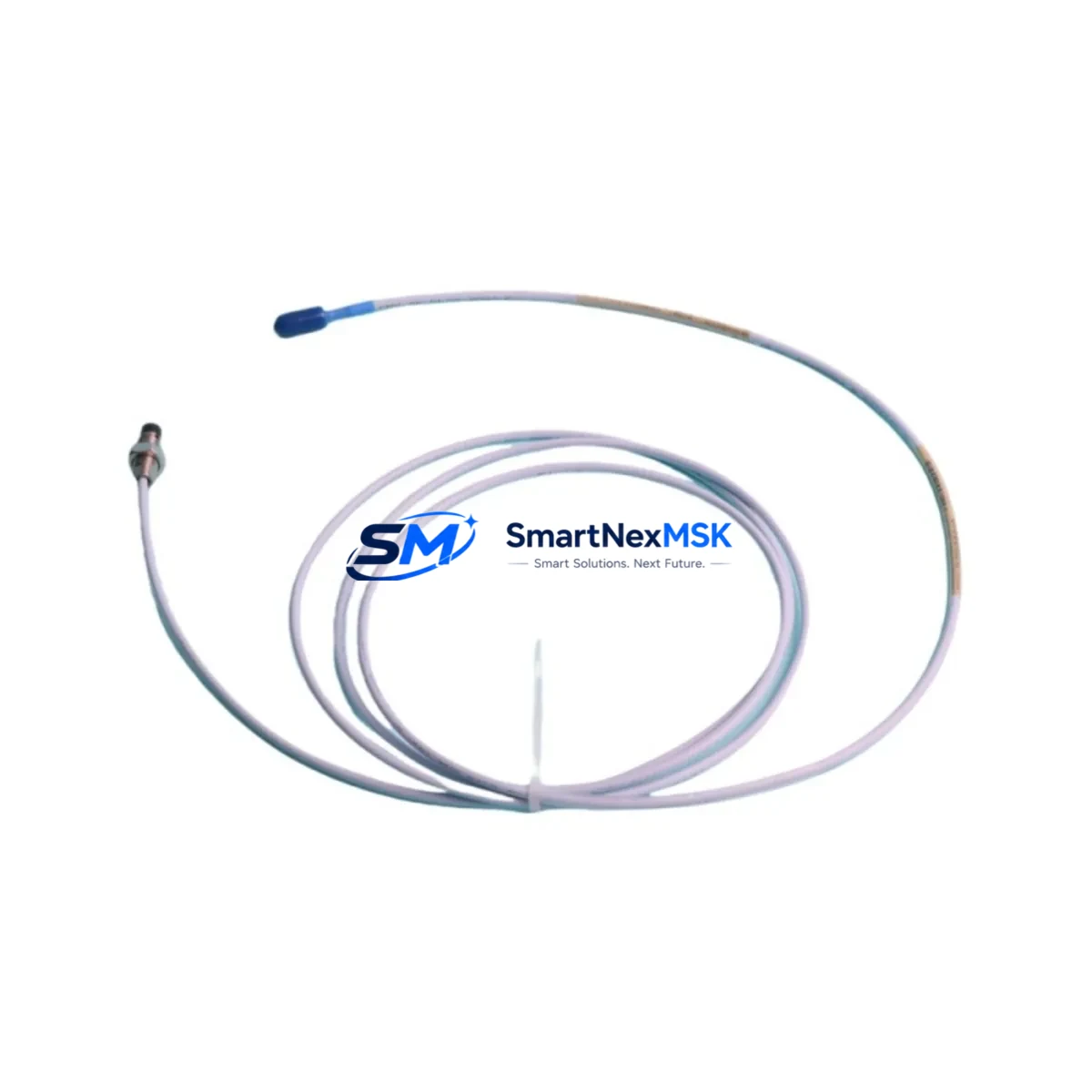
| Probe Type | 8mm Eddy Current Proximity Probe |
| Probe Length | 23 inches (584 mm) integral cable |
| Sensitivity | 200 mV/mil (7.87 V/mm) |
| Linear Range | 0 to 90 mil (0 to 2.29 mm) |
| Supply Voltage | -24 VDC (nominal) |
| Operating Temperature | -35°C to +120°C (probe tip) |
| Connector Type | CN (Coaxial, standard 3300 XL) |
| Compatible Driver/Barrier | 3300 XL 8mm Proximitor Sensor (e.g. 330180 series) |
| Compatible Monitor | 3300/16 Dual Voting, 3500/40M, 3500/42M, 3500/45 |
| Application | Radial vibration, axial position, differential expansion |
| Installation Environment | Hazardous area rated; oil mist, high-temperature bearing housings |
| Maintenance Recommendation | Replace at first sign of output drift, cable damage, or gap voltage anomaly |
| Warranty | 12 Months from shipment date |
| Pre-shipment Test | Yes — output sensitivity and gap voltage verified |
Maintenance Planning for Continuous Operation
When a 330101-00-23-90-02-CN probe is flagged during a routine control cabinet inspection or condition monitoring review, experienced maintenance engineers know that replacing the probe alone is rarely sufficient for a complete corrective action. The 3300 XL measurement chain is a tightly coupled system, and any component along the signal path can introduce measurement error or cause a spurious trip.
Begin by verifying the paired 330180-91-00 Proximitor Sensor (the signal conditioning driver). A probe that has experienced a mechanical impact or thermal excursion may have induced impedance changes that stress the driver output stage. Check the driver’s DC output voltage at the monitor input terminal — it should fall within the linear range specified for the gap distance in use. If the output is saturated or erratic, the Proximitor Sensor should be replaced concurrently.
Next, inspect the 330130 extension cable connecting the probe to the Proximitor. Extension cable shield continuity and connector seating are frequent sources of intermittent faults that mimic probe failure. In high-vibration environments, cable armor fatigue at the conduit entry point is a known failure mode. Carry a spare extension cable of the correct length in your critical spares kit alongside the probe.
At the monitor rack level, confirm that the 3500/40M Proximitor/Seismic Monitor or 3500/42M Proximitor Monitor channel is reading correctly after probe replacement. Use the monitor’s front-panel OK/NOT OK indicators and the System 1 software trend data to validate the new probe’s gap voltage and dynamic output before returning the machine to service. If the channel remains in NOT OK state after probe replacement, suspect the monitor card itself — the 3500/40M I/O module and its associated terminal board should be on your inspection checklist.
For facilities running the older 3300/16 Dual Voting Monitor, confirm that the replacement probe’s sensitivity matches the monitor’s configured scale factor. Mismatched sensitivity between the probe and monitor configuration is a common commissioning error that produces incorrect vibration readings without triggering a hardware fault alarm.
Power supply integrity is equally critical. The 3500/15 Power Supply or equivalent rack power module should be verified to deliver stable -24 VDC to the Proximitor. Voltage sag under load — particularly in aging racks with multiple channels populated — can shift the probe’s operating point and introduce measurement offset. A 3500/05 Rack Interface Module with a degraded power regulation circuit is a less obvious but real contributor to probe measurement anomalies.
In facilities with intrinsically safe installations, the associated Zener barrier or galvanic isolator in the IS circuit must be inspected for correct entity parameters and continuity. A barrier with a blown fuse element will present as a probe failure at the monitor. Always carry spare barriers matched to the 3300 XL probe’s entity parameters in your IS cabinet spare parts inventory.
Finally, for machines where the 330101-00-23-90-02-CN is used for axial position or differential expansion measurement, verify the thrust bearing clearance and confirm that the new probe’s zero-reference gap voltage is correctly documented in the machine’s maintenance record. Incorrect gap setting after probe replacement is a leading cause of nuisance trips during machine restart.
Site Replacement Workflow
Step 1 — Isolation and Permit: Obtain a hot-work or confined-space permit as applicable. Isolate the monitor channel (place in bypass mode via System 1 or the rack keyswitch) to prevent a spurious trip during probe removal. Document the existing gap voltage reading before disconnection.
Step 2 — Probe Removal: Disconnect the extension cable at the Proximitor end first. Unthread the probe from the bearing housing bracket using the correct spanner. Note the number of turns to removal — this gives a reference for reinstallation gap setting.
Step 3 — Visual Inspection: Inspect the probe tip for mechanical damage, corrosion, or oil contamination. Inspect the integral cable for kinking, abrasion, or connector damage. If the cable jacket is compromised, do not reinstall — replace the full probe assembly.
Step 4 — New Probe Installation: Thread the 330101-00-23-90-02-CN into the bracket to the documented turn count. Connect the extension cable. Apply power and measure the gap voltage at the Proximitor output. Adjust the probe gap to achieve the target gap voltage per the machine’s original commissioning record (typically 10.0 VDC ± 0.5 VDC for a standard 50 mil gap).
Step 5 — Functional Verification: With the monitor channel still in bypass, observe the dynamic vibration reading. Rotate the shaft by hand if accessible, or use a calibrated signal source to verify the channel’s dynamic response. Confirm OK status on the monitor before removing bypass.
Step 6 — Return to Service: Remove bypass, confirm OK status, and document the replacement in the machine’s maintenance management system (CMMS). Update the spare parts inventory to trigger reorder of the consumed probe.
Spare Parts Support FAQ
Q1: Is the 330101-00-23-90-02-CN a direct drop-in replacement for older 330101 series probes?
The 330101-00-23-90-02-CN is dimensionally and electrically compatible with other 330101 series 8mm probes of the same cable length and connector type. However, always verify the sensitivity specification (200 mV/mil) matches the monitor channel’s configured scale factor before installation. If the monitor was configured for a different sensitivity, a reconfiguration via System 1 software is required.
Q2: What is the recommended spare parts stocking strategy for 3300 XL proximity probes?
For critical rotating machinery (turbines, compressors, pumps), industry best practice recommends stocking a minimum of one probe per monitored shaft position as a critical spare, plus one Proximitor Sensor and one extension cable per machine train. For facilities with multiple identical machines, a pooled critical spare of 2–3 probes per probe model is a cost-effective approach that balances inventory carrying cost against downtime risk.
Q3: How is each unit tested before shipment?
Each 330101-00-23-90-02-CN unit is bench-tested prior to shipment using a calibrated test fixture that verifies output sensitivity (mV/mil), gap voltage linearity across the full linear range, and cable/connector continuity. A test report is available upon request. Units that do not meet Bently Nevada’s original specification are not shipped.
Q4: What does the 12-month warranty cover?
The 12-month warranty covers manufacturing defects, output sensitivity out-of-specification, and cable/connector integrity failures under normal installation and operating conditions. It does not cover damage resulting from mechanical impact, incorrect gap setting beyond the linear range, or installation in environments exceeding the probe’s rated temperature or chemical exposure limits. Warranty claims are processed with return shipment and replacement or full refund at the buyer’s option.
© 2026 SMARTNEXMSK. All rights reserved.
Original Source: https://smartnexmsk.com
Contact: sales@smartnexmsk.com | +86 18259474341


