Bently Nevada 330101-00-25-10-01-00 Maintenance-Ready Spare for 3300 XL Automation
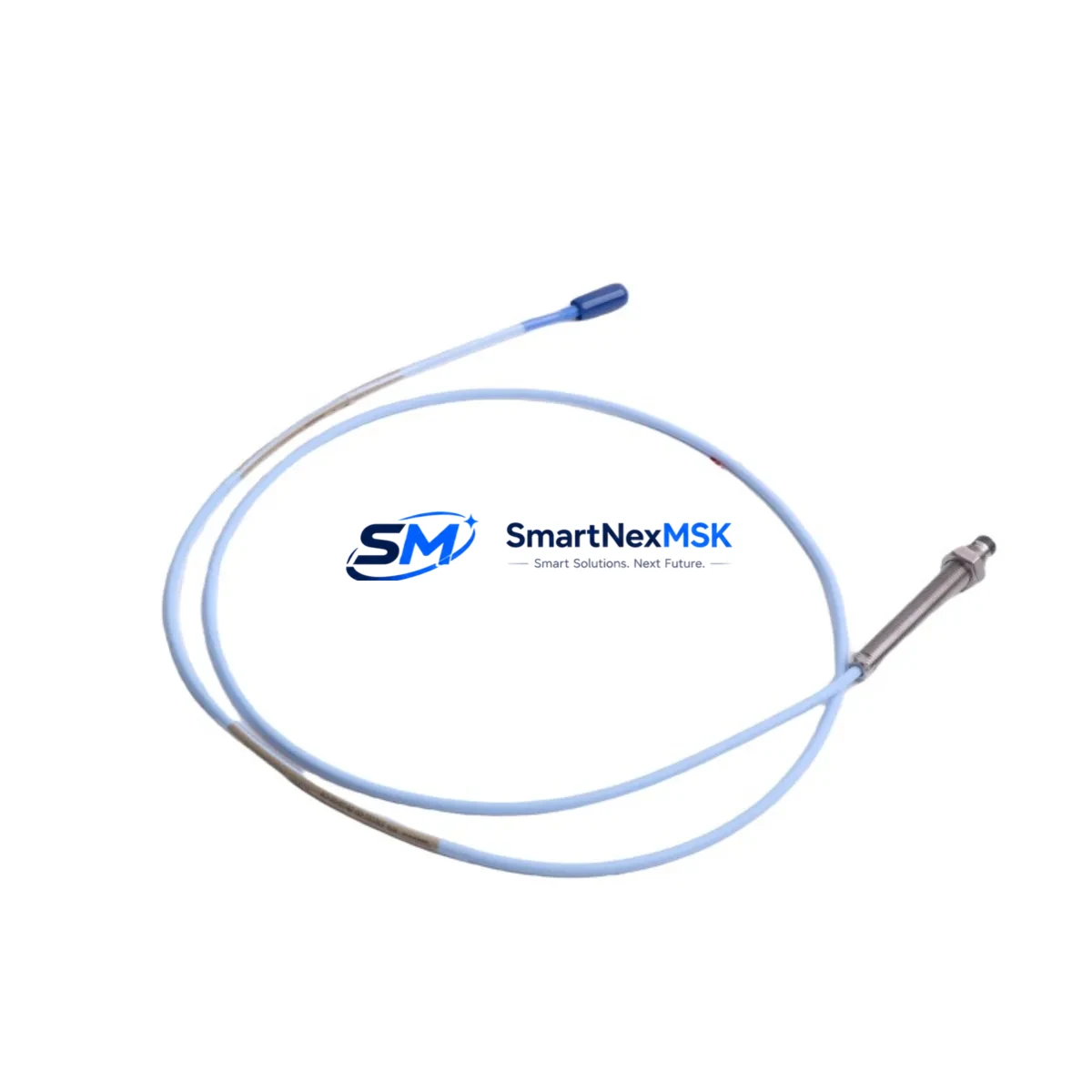
The Bently Nevada 330101-00-25-10-01-00 is an 8mm eddy current proximity probe engineered for the 3300 XL Series vibration monitoring system — one of the most widely deployed machinery protection platforms in rotating equipment applications worldwide. Whether you are managing a planned turnaround, responding to an unplanned trip, or building a critical spare inventory for a compressor train or turbine skid, this probe is a direct maintenance-ready replacement that restores system integrity without reconfiguration or recalibration of the signal conditioning chain.
Maintenance engineers and reliability teams operating Baker Hughes / Bently Nevada 3300 XL systems understand that proximity probe availability is non-negotiable. A failed or degraded probe can trigger a false machinery trip, mask a real vibration event, or force an unplanned shutdown that costs far more than the probe itself. Stocking the 330101-00-25-10-01-00 as a certified spare eliminates that risk and keeps your machinery protection loop fully operational.
Spare Maintenance Table
| Parameter | Specification |
|---|---|
| Part Number / SKU | 330101-00-25-10-01-00 |
| Brand | Bently Nevada (Baker Hughes) |
| Series | 3300 XL |
| Probe Type | Eddy Current Proximity Probe |
| Probe Diameter | 8 mm |
| Cable Length | 25 cm (integral cable) |
| Connector Type | 10-32 UNF coaxial |
| Sensitivity | 7.87 V/mm (200 mV/mil) |
| Linear Range | 0.25 – 2.25 mm (10 – 90 mil) |
| Operating Temperature | -35°C to +177°C |
| Target Material | AISI 4140 steel (standard) |
| Application | Radial vibration, axial position, speed sensing |
| Compatible Driver/Conditioner | 3300 XL 8mm Extension Cable + 3300 XL Proximitor® Sensor |
| Compatibility | Direct replacement for 3300 XL machinery protection systems |
| Origin | USA |
| Warranty | 12 Months |
| Condition | Original Spare — tested and inspected before shipment |
Maintenance Planning for Continuous Operation
When replacing the 330101-00-25-10-01-00 in the field, a disciplined maintenance engineer does not stop at the probe itself. The 3300 XL measurement chain is a system — and a degraded component anywhere in the loop can compromise the integrity of the entire vibration monitoring circuit. During the same maintenance window, inspect and verify the following associated components:
The 3300 XL Extension Cable (typically 330130-series) connects the probe to the Proximitor® sensor and is subject to mechanical fatigue, connector corrosion, and insulation breakdown in high-temperature or high-vibration environments. Replace it if continuity or impedance readings are out of tolerance. The 3300 XL Proximitor® Sensor (330180-series) provides the oscillator/demodulator function and should be bench-tested for output linearity whenever a probe is replaced — a failing Proximitor can mimic probe failure symptoms. Check the I/O terminal block and field wiring at the junction box for loose terminations, moisture ingress, and shield grounding integrity, as ground loops are a leading cause of noise-induced false trips.
At the rack level, verify the 3500/42M Proximitor®/Seismic Monitor or equivalent 3300 rack monitor card for alarm setpoint integrity and channel health. Inspect the 3500 rack power supply module for output voltage stability — an under-voltage condition can shift probe gap voltage and produce erroneous vibration readings. If the system includes a 3500/20 Rack Interface Module (RIM) for Modbus or Ethernet communication, confirm that the channel data is being correctly transmitted to the DCS or historian after probe replacement.
For installations where the probe monitors axial shaft position in addition to radial vibration, cross-check the thrust position monitor channel and verify that the gap voltage is within the linear range after reinstallation. In compressor or steam turbine applications, also inspect the Keyphasor® transducer (330980-series) and its associated signal cable, as phase reference integrity is critical for vector-based vibration analysis. Finally, review the barrier or isolator modules in the intrinsically safe circuit (if applicable) and confirm that the zener barriers or galvanic isolators are within their rated parameters — degraded isolation can introduce common-mode noise that masks real machinery faults.
Site Replacement Workflow
Step 1 — Pre-replacement verification: Record the existing gap voltage (typically –10.0 VDC ± 0.5 V at nominal gap) and compare against the system baseline. Document the current vibration amplitude and DC gap readings from the monitor display or DCS historian before breaking the circuit.
Step 2 — Safe isolation: Follow your site LOTO procedure. For non-trip-critical channels, coordinate with the control room to place the channel in bypass mode to prevent a spurious machinery trip during probe removal. For trip-critical channels, confirm with operations before proceeding.
Step 3 — Physical replacement: Remove the probe from the bracket, disconnect the extension cable at the field junction box, and install the 330101-00-25-10-01-00 in the same mounting position. Torque the probe body to the manufacturer’s specification and reconnect the extension cable, ensuring the coaxial connector is fully seated and the locking nut is finger-tight plus one-quarter turn.
Step 4 — Gap setting and verification: Adjust the probe gap to achieve the target DC output voltage per the system calibration record. Use a calibrated digital voltmeter at the Proximitor® output terminals. Confirm the reading is stable and within the linear range before releasing the channel from bypass.
Step 5 — Functional test and documentation: Verify that the monitor channel displays a healthy vibration reading consistent with the machine’s normal operating baseline. Update the maintenance record with the replacement date, new probe serial number, gap voltage as-found and as-left, and technician sign-off. This documentation supports both reliability analysis and warranty claims.
This workflow minimizes downtime, preserves system compatibility, and ensures that the replacement probe is performing correctly before the machine is returned to service — reducing the risk of a repeat trip or a missed fault condition.
Spare Parts Support FAQ
Q1: Is the 330101-00-25-10-01-00 a direct drop-in replacement for my existing 3300 XL probe?
Yes. The 330101-00-25-10-01-00 is a direct replacement for the 3300 XL 8mm proximity probe family. It maintains the same sensitivity (7.87 V/mm), connector standard (10-32 UNF), and linear range, so no recalibration of the Proximitor® sensor or monitor card is required — only a gap adjustment to restore the nominal DC output voltage.
Q2: How do you verify compatibility before shipment?
Each unit is inspected against the original part number and series documentation before dispatch. We verify probe impedance, cable continuity, and connector integrity. A test report is available upon request. All units ship with a 12-month warranty covering manufacturing defects and functional performance.
Q3: What is your lead time and inventory strategy for critical spare parts?
We maintain stock of high-demand 3300 XL series components to support emergency replacement scenarios. Standard orders ship within 1–3 business days. For sites managing a critical spare inventory program, we recommend holding a minimum of one probe per monitored shaft, plus one extension cable set, to cover both planned and unplanned replacement events without waiting on procurement lead times.
Q4: What should I do if the replacement probe does not restore the expected gap voltage?
First, verify that the extension cable is undamaged and that the Proximitor® sensor is functioning correctly by checking its output with a known-good probe. If the Proximitor® output is within specification with a test probe but not with the installed probe, inspect the probe mounting bracket for mechanical damage or contamination on the target surface. Contact our technical support team with your gap voltage readings and system configuration — we will assist with root cause analysis and, if the unit is found to be defective within the warranty period, arrange a replacement at no charge.
© 2026 SMARTNEXMSK. All rights reserved.
Original Source: https://smartnexmsk.com
Contact: sales@smartnexmsk.com | +86 18259474341


