Bently Nevada 330101-00-25-20-12-05 Spare 3300 XL: Precision Replacement for Vibration Monitoring Systems
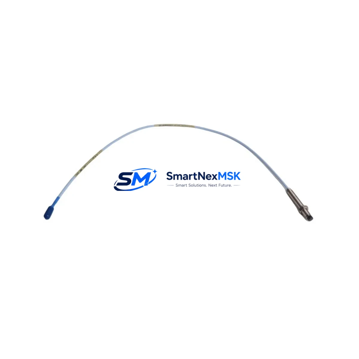
The Bently Nevada 330101-00-25-20-12-05 is an 8mm proximity probe engineered for the 3300 XL Series continuous vibration monitoring platform. As a maintenance-ready original spare, this probe is designed to restore full measurement integrity in rotating machinery protection systems with minimal downtime. Whether you are responding to an unplanned trip, executing a scheduled turnaround, or building a critical-path spare parts inventory, the 330101-00-25-20-12-05 delivers the dimensional accuracy, gap voltage linearity, and EMI shielding required by Bently Nevada’s eddy-current sensing architecture.
Maintenance engineers working on steam turbines, gas compressors, centrifugal pumps, and large induction motors rely on the 3300 XL system to provide continuous radial vibration, axial position, and differential expansion data. A failed or degraded proximity probe can mask developing faults, trigger nuisance trips, or—worse—allow a genuine machinery fault to go undetected. Stocking a verified original replacement such as the 330101-00-25-20-12-05 is therefore not optional; it is a fundamental element of any reliability-centered maintenance programme.
Before replacing this probe, maintenance and procurement engineers should audit the complete measurement chain. The 330101-00-25-20-12-05 operates as part of a three-component system: the probe itself, a compatible extension cable (typically the 330130 series), and a proximitor/driver module such as the 3300 XL 8mm Proximitor (330180 series). All three components must be matched in cable length and system configuration to maintain the calibrated scale factor of 200 mV/mil (7.87 V/mm). Replacing only the probe while leaving a degraded extension cable or a proximitor with a drifting power supply in service will not restore system accuracy.
Spare Maintenance Table
| Parameter | Specification |
|---|---|
| Part Number | 330101-00-25-20-12-05 |
| Series | Bently Nevada 3300 XL |
| Probe Diameter | 8 mm |
| Cable Length | 25 ft (7.62 m) integral cable |
| Thread Size | M10 × 1.0 |
| Scale Factor | 200 mV/mil (7.87 V/mm) |
| Operating Gap Range | 0.25 – 2.25 mm (10 – 90 mil) |
| Supply Voltage | −24 VDC (nominal) |
| Temperature Range | −35 °C to +121 °C |
| Target Material Compatibility | AISI 4140 steel (standard); other alloys require recalibration |
| Connector | 3-pin MIL-C-5015 style |
| IP Rating | IP67 (probe tip and body) |
| Compatibility | 3300 XL 8mm Proximitor, 3300 XL Rack, System 1 software |
| Condition | Original, new or recertified; tested prior to shipment |
| Warranty | 12 Months from date of shipment |
| Lead Time | In-stock: ships within 24–48 hours |
Maintenance Planning for Continuous Operation
A structured spare parts strategy for the 3300 XL measurement chain should extend beyond the probe itself. When the 330101-00-25-20-12-05 is flagged for replacement during a control cabinet inspection or a machinery health review, the following associated components should be evaluated concurrently to avoid repeat outages:
- 330130-080-00-00 Extension Cable (8 m): The integral cable on the 330101 terminates at the proximitor via an extension cable. Inspect for jacket abrasion, connector corrosion, and continuity. A cracked or moisture-ingressed extension cable will introduce noise into the gap voltage signal even with a new probe installed.
- 330180-X1-05 Proximitor / Driver Module: The 3300 XL 8mm Proximitor converts the probe’s oscillator signal to a DC voltage proportional to gap. Verify supply rail stability (−24 VDC ±10%) and output linearity. A proximitor with a failing oscillator circuit will produce erratic OK/Not-OK relay outputs regardless of probe condition.
- 3300/16-XX-XX-XX-XX-XX I/O Module: The 3300 XL rack I/O module receives the proximitor output and routes it to the monitor card. Inspect terminal block torque, check for oxidised contacts, and confirm that the channel is not in bypass mode.
- 3300/20 Dual Voting Logic Module: In two-out-of-three voting configurations, a single failed probe channel can alter the trip logic. Confirm that the voting module firmware version is compatible with the replacement probe’s scale factor.
- 3300/55 Power Supply Module: The rack power supply feeds all proximitor modules. Measure output ripple and confirm redundant supply switchover is functional. A degraded power supply is a common root cause of simultaneous multi-channel probe faults.
- 3300/46M Keyphasor Module: If the machine uses a Keyphasor signal for phase reference (1× and 2× vibration analysis), inspect the Keyphasor probe and its dedicated proximitor alongside the radial probes. A missing or noisy Keyphasor signal will corrupt vector data in System 1.
- Relay Output Module (3300/32 or 3300/34): Verify that the alarm and trip relay contacts are not welded or corroded. A stuck relay can prevent a legitimate trip from reaching the shutdown system.
- Terminal Blocks and Grounding Bars: Loose or corroded terminal connections in the junction box between the probe cable and the rack are a frequent source of intermittent faults. Re-torque all terminals and verify single-point grounding of the probe cable shield.
Procurement engineers should note that the 330101-00-25-20-12-05 is a long-lifecycle part with a stable form factor, making it suitable for multi-unit blanket orders. Holding a minimum of two probes per critical machine train is a widely adopted practice in petrochemical and power generation facilities operating under API 670 machinery protection standards.
Site Replacement Workflow
Replacing the 330101-00-25-20-12-05 in the field follows a defined sequence to minimise downtime and avoid introducing new faults:
- Bypass and Notify: Place the affected channel in bypass mode at the 3300 XL monitor card and notify the control room. Document the bypass in the permit-to-work system.
- De-energise and Disconnect: Remove power from the proximitor module before disconnecting the probe cable. Eddy-current probes are not hot-swap devices; disconnecting under power can damage the proximitor oscillator circuit.
- Remove the Old Probe: Unthread the probe from the bracket using the correct spanner size (M10 × 1.0). Note the installed gap (typically 1.0–1.5 mm for steel targets) using a feeler gauge or the proximitor’s DC output voltage before removal.
- Install the Replacement: Thread the 330101-00-25-20-12-05 into the bracket and set the gap to the documented value. Tighten the locknut to the specified torque (typically 5–7 N·m). Route the cable to avoid contact with hot surfaces or rotating components.
- Reconnect and Verify: Reconnect the extension cable and restore power to the proximitor. Measure the DC gap voltage at the proximitor output (target: −10.0 VDC ±0.5 V at nominal gap for a 200 mV/mil system). Confirm the OK relay is energised.
- Remove Bypass and Test: Remove the channel bypass, confirm alarm and trip setpoints are active, and perform a functional test by simulating a gap change. Log the as-left gap voltage in the maintenance management system.
- System 1 Verification: If the plant uses Bently Nevada System 1 condition monitoring software, confirm that the channel is receiving valid data and that no latched alarms remain active.
This workflow is compatible with both hot-standby redundant installations and single-channel configurations. For legacy 3300 Series racks (non-XL), dimensional compatibility should be verified before installation, as the 330101-00-25-20-12-05 is optimised for the 3300 XL platform.
Spare Parts Support FAQ
Q1: Is the 330101-00-25-20-12-05 compatible with older 3300 Series (non-XL) racks?
The 330101-00-25-20-12-05 is designed and calibrated for the 3300 XL 8mm Proximitor system. While the physical probe dimensions are similar to earlier 3300 Series probes, the scale factor and OK threshold voltages are optimised for the XL proximitor. Using this probe with a non-XL proximitor may result in calibration errors. Always verify the proximitor model number before installation.
Q2: What testing is performed before shipment?
Each 330101-00-25-20-12-05 unit is bench-tested for DC gap voltage linearity across the full operating gap range (0.25–2.25 mm), OK relay output, and cable continuity before dispatch. A test report is available upon request. Units are shipped in anti-static packaging with protective caps on the probe tip and connector.
Q3: How should this spare be stored in a warehouse environment?
Store the probe in its original packaging in a dry, temperature-controlled environment (0–40 °C, <85% RH non-condensing). Avoid storing near strong magnetic fields or high-frequency RF sources, which can affect the probe’s ferrite core. Inspect the connector and cable jacket annually if the spare is held for more than 12 months.
Q4: What does the 12-month warranty cover?
The 12-month warranty covers manufacturing defects, premature electrical failure under normal operating conditions, and dimensional non-conformance. It does not cover damage resulting from incorrect installation gap, over-torquing the locknut, cable damage from mechanical contact, or use with incompatible proximitor models. Warranty claims are processed within 5 business days of receipt of the returned unit.
© 2026 SMARTNEXMSK. All rights reserved.
Original Source: https://smartnexmsk.com
Contact: sales@smartnexmsk.com | +86 18259474341


