Bently Nevada 330101-00-33-10-12-05 3300 XL Spare: Precision Replacement for Vibration Monitoring Systems
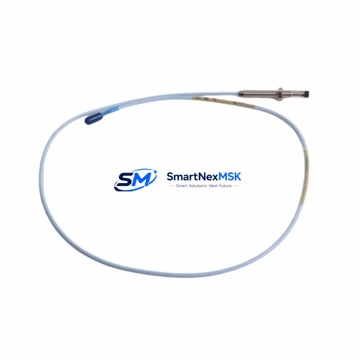
The Bently Nevada 330101-00-33-10-12-05 is an original 8mm eddy-current proximity transducer engineered for the 3300 XL Series continuous vibration monitoring platform. In rotating machinery protection systems — turbines, compressors, pumps, and gearboxes — this transducer is the primary sensing element responsible for converting shaft displacement into a calibrated voltage signal. When this component degrades or fails, the entire vibration channel goes blind, exposing critical rotating assets to undetected mechanical faults and catastrophic unplanned shutdowns.
For maintenance engineers managing condition monitoring infrastructure, stocking a verified replacement of the 330101-00-33-10-12-05 is not optional — it is a fundamental element of any credible spare parts strategy. This listing provides an original, factory-specification transducer with full compatibility confirmation for the 3300 XL system architecture, tested prior to dispatch and backed by a 12-month warranty.
Spare Maintenance Table
| Parameter | Specification |
|---|---|
| Part Number | 330101-00-33-10-12-05 |
| Brand | Bently Nevada |
| Series | 3300 XL |
| Transducer Type | Eddy-Current Proximity Transducer |
| Probe Diameter | 8 mm |
| Cable Length | 1.0 m (extension cable required for full system) |
| Armored Cable | Yes (05 suffix) |
| Sensitivity | 7.87 V/mm (200 mV/mil) |
| Linear Range | 0.25 mm – 2.25 mm (10 – 90 mil) |
| Supply Voltage | −24 VDC (via driver/oscillator) |
| Operating Temperature | −35°C to +121°C |
| Target Material Compatibility | Steel, Stainless Steel, Inconel |
| System Compatibility | 3300 XL 8mm System (Proximitor, Extension Cable, Transducer) |
| Mounting | M10 × 1 threaded body |
| Application | Radial vibration, axial position, differential expansion |
| Condition | Original, new or reconditioned-to-spec |
| Pre-shipment Testing | Yes — output voltage, sensitivity, and linearity verified |
| Warranty | 12 Months |
| Origin | USA |
Maintenance Planning for Continuous Operation
The 330101-00-33-10-12-05 transducer does not operate in isolation. It is the field-end component of a three-part measurement chain: the transducer itself, a matched extension cable (typically the 330130 series in 5m or 9m lengths), and a Proximitor sensor such as the 330180 or 330185, which provides the oscillator/demodulator function and outputs the DC voltage signal to the monitoring rack. When replacing the transducer, maintenance engineers must inspect and verify the condition of all three elements — a degraded extension cable connector or a drifting Proximitor will invalidate the calibration of a new transducer and produce false readings.
At the rack level, the signal feeds into a 3300/16 or 3300/20 monitor card housed in the 3300 Rack system. These monitor cards should be inspected for firmware revision compatibility and channel configuration when a transducer swap is performed. If the plant is running an older rack revision, confirm that the channel is configured for the 8mm transducer system and not a legacy 5mm or 11mm probe type.
During planned outages, it is best practice to simultaneously inspect the 3300/05 Power Supply module that feeds the monitoring rack. A marginal power supply delivering slightly off-spec −24 VDC will cause the Proximitor to output erratic signals even with a new transducer installed. Carry a calibrated DC voltmeter and verify supply rail voltage at the rack terminal block before declaring the replacement successful.
For machines with both radial and axial measurement requirements, the axial channel typically uses a 330101-00-33-10-12-05 or a similar 8mm probe configured for thrust position monitoring. Inspect the paired axial transducer and its 330130 extension cable at the same time to avoid a second outage window within the same maintenance cycle.
In control cabinets where the 3300 XL rack is co-located with relay output modules — such as the 3300/55 Relay Module — verify that the relay setpoints and time delays are correctly configured after the transducer replacement. A new transducer with slightly different gap voltage at the installed position may cause nuisance trips if the OK relay threshold is not re-verified.
For facilities managing legacy systems approaching end-of-support, stocking a minimum of two units of the 330101-00-33-10-12-05 per critical machine train is recommended. Pair this with a spare 330130 extension cable, a spare 330180 Proximitor, and a spare 3300/16 monitor card to form a complete channel replacement kit. This approach eliminates diagnostic ambiguity during emergency shutdowns — swap the entire channel, restore operation, then diagnose the failed component offline.
Site Replacement Workflow
Step 1 — Isolation and Documentation: Before removing the existing transducer, record the installed gap voltage (typically −10 VDC ± 0.5 V for a correctly gapped 8mm probe on steel). This baseline confirms the new transducer is gapped correctly after installation. Isolate the channel at the monitor rack by placing the channel in bypass mode to prevent spurious trip signals during the swap.
Step 2 — Physical Removal: Using the correct spanner for the M10 × 1 threaded body, back out the transducer from the bracket. Inspect the bracket bore for wear, corrosion, or thread damage. A damaged bracket will prevent correct gap setting and must be replaced before installing the new transducer.
Step 3 — Cable Inspection: Disconnect the transducer from the extension cable at the field junction. Inspect the TNC connector for pin damage, corrosion, or contamination. Clean with contact cleaner if necessary. If the connector shows mechanical damage, replace the extension cable — do not install a new transducer on a damaged cable.
Step 4 — Installation and Gapping: Thread the new 330101-00-33-10-12-05 into the bracket by hand until snug. Connect the extension cable. Power the Proximitor and monitor the output voltage with a calibrated meter. Adjust the transducer gap until the output reads within the linear range center (approximately −10 VDC for a steel target). Lock the transducer with the jam nut to the torque specification in the Bently Nevada installation manual.
Step 5 — System Verification: Remove the channel bypass at the rack. Confirm the OK LED illuminates on the monitor card. Verify the vibration reading is within expected baseline for the machine at rest or at operating speed. Log the new gap voltage and date of replacement in the maintenance management system. The 12-month warranty period begins from the date of installation.
Spare Parts Support FAQ
Q: Is the 330101-00-33-10-12-05 compatible with both the 3300 XL and older 3300 Series racks?
A: The 330101-00-33-10-12-05 is designed and calibrated for the 3300 XL 8mm system. While the physical connector is compatible with older 3300 Series Proximitors, sensitivity and linearity specifications are optimized for the XL-generation oscillator/demodulator. For legacy 3300 (non-XL) racks, verify the Proximitor part number before installation to confirm calibration compatibility.
Q: What pre-shipment testing is performed on each unit?
A: Every 330101-00-33-10-12-05 unit is bench-tested prior to dispatch. Testing covers output voltage at nominal gap, sensitivity (mV/mil), linearity across the full measurement range, and cable/connector continuity. A test report is available upon request. Units that do not meet factory specification are not shipped.
Q: What does the 12-month warranty cover?
A: The 12-month warranty covers manufacturing defects, premature electrical failure under normal operating conditions, and out-of-specification sensitivity at the time of installation. It does not cover physical damage from incorrect installation, chemical contamination, or operation outside the specified temperature and voltage range. Warranty claims are supported with a replacement unit dispatched after fault confirmation.
Q: How should this spare be stored if not immediately installed?
A: Store the 330101-00-33-10-12-05 in its original packaging in a dry, temperature-controlled environment (10°C – 40°C, <70% RH non-condensing). Protect the TNC connector with the supplied cap. Do not store near strong magnetic fields or solvents. Shelf life under correct storage conditions exceeds 5 years. Inspect the connector and cable jacket before installation if the unit has been in storage for more than 12 months.
© 2026 SMARTNEXMSK. All rights reserved.
Original Source: https://smartnexmsk.com
Contact: sales@smartnexmsk.com | +86 18259474341


