Bently Nevada 330101-00-35-05-02-05 Maintenance-Ready Spare for 3300 XL Automation
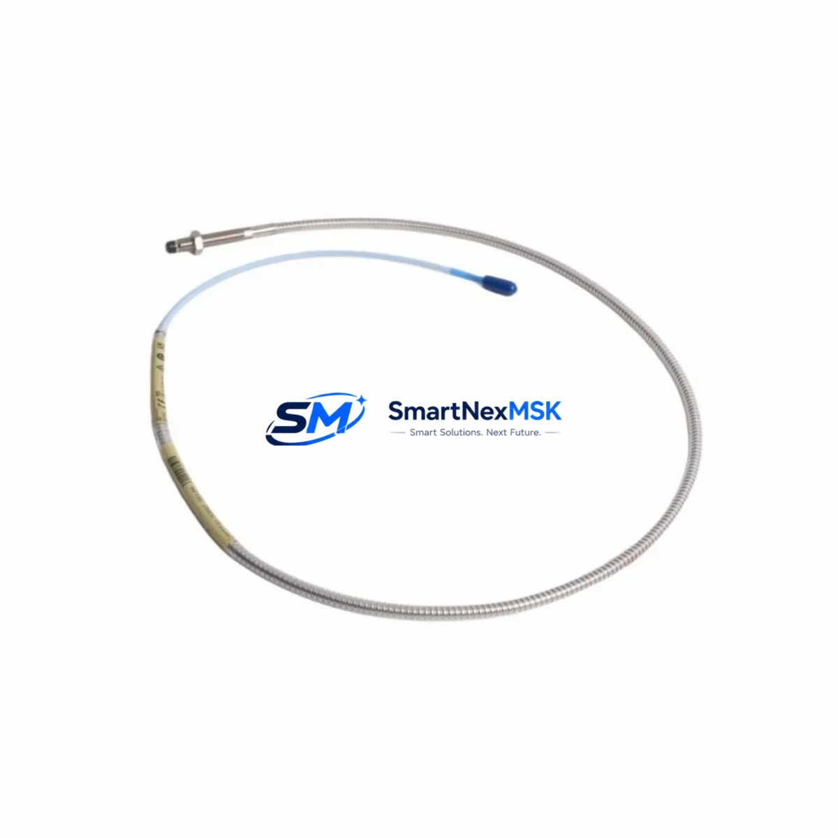
The Bently Nevada 330101-00-35-05-02-05 is an original 8mm Eddy-Current Proximity Transducer engineered for the 3300 XL Series continuous vibration monitoring system. In rotating machinery protection environments — turbines, compressors, pumps, and gearboxes — this transducer is a front-line component whose failure directly triggers unplanned shutdown events. Holding a verified spare on the shelf is not optional; it is a core element of any credible predictive maintenance and rapid-recovery strategy.
For maintenance engineers managing critical rotating assets, the 330101-00-35-05-02-05 represents the sensing element in a complete measurement chain. Its 8mm tip diameter, 200 mV/mil sensitivity, and -24 VDC bias voltage output are precisely matched to the 3300 XL monitor rack. When this transducer is replaced in the field, the entire signal path — from the probe tip through the extension cable to the proximitor — must be treated as a system, not as isolated components. A replacement transducer paired with a mismatched or aged extension cable will produce calibration drift and false alarms, defeating the purpose of the repair.
Sourced directly from authorized supply channels, each unit shipped by SMARTNEXMSK is individually tested for output linearity, gap voltage response, and connector integrity before dispatch. All units carry a 12-month warranty covering manufacturing defects and functional performance under specified operating conditions.
Spare Maintenance Table
| Parameter | Specification |
|---|---|
| Part Number | 330101-00-35-05-02-05 |
| Brand | Bently Nevada |
| Series | 3300 XL |
| Type | 8mm Eddy-Current Proximity Transducer |
| Sensitivity | 200 mV/mil (7.87 V/mm) |
| Bias Voltage Output | -24 VDC (nominal) |
| Operating Gap Range | 0.25 mm – 2.25 mm (10 – 90 mil) |
| Supply Voltage | -24 VDC ± 1 VDC |
| Operating Temperature | -35°C to +120°C |
| Cable Length (Probe Body) | 0.35 m (standard) |
| Connector Type | 5-pin MIL-C-5015 compatible |
| Compatibility | 3300 XL Proximitor / Monitor Rack |
| Application | Radial vibration, axial position, differential expansion monitoring |
| Origin | USA |
| Warranty | 12 Months — tested before shipment |
Maintenance Planning for Continuous Operation
When a 330101-00-35-05-02-05 transducer is flagged for replacement during a planned outage or emergency shutdown, the scope of inspection should extend well beyond the probe itself. Experienced maintenance engineers treat this event as an opportunity to audit the full vibration monitoring loop and adjacent control infrastructure.
Begin with the 330130-080-00-05 extension cable — the 8-meter armored cable that connects the probe body to the proximitor. Extension cables accumulate mechanical fatigue at conduit entry points and connector terminations; a transducer replacement paired with a degraded cable will not restore measurement accuracy. Inspect the cable jacket, verify continuity, and replace if shielding integrity is in doubt.
The 330180-X1-05 Proximitor sensor (or equivalent 3300 XL series proximitor) should be bench-tested for output voltage linearity at the time of transducer replacement. Proximitor drift is a common root cause of nuisance trips that are incorrectly attributed to the transducer. Confirm the proximitor’s gap voltage output matches the calibration chart for the 330101 probe series.
At the 3300/16 or 3300/20 monitor rack level, verify that channel configuration parameters — full-scale range, alert and danger setpoints, and OK relay logic — remain consistent with the replacement transducer’s sensitivity specification. A configuration mismatch after hardware replacement is a documented source of post-maintenance false trips.
For installations where the 330101-00-35-05-02-05 is used in axial position or differential expansion measurement, also inspect the 3300/55 Dual Voting Logic module and associated relay output wiring. Confirm that the voting logic is not masking a latent fault on a parallel channel.
Power supply integrity is critical. The 3300 XL system power supply module should be load-tested during the outage window. A power supply operating near its rated output capacity under full rack load is a common contributor to intermittent transducer signal anomalies. If the facility uses a redundant power supply configuration, verify automatic switchover function.
In control cabinets housing the 3300 XL rack alongside other instrumentation, inspect terminal blocks and field wiring terminations for corrosion, loose screws, and insulation degradation — particularly in high-vibration or high-humidity environments. Loose terminations at the monitor rack’s field wiring connector are a frequent source of signal noise that mimics transducer failure.
For facilities running legacy Bently Nevada 3300 (non-XL) series monitors alongside newer 3300 XL racks, confirm that the replacement 330101-00-35-05-02-05 is not inadvertently installed in a non-XL channel. The 3300 XL proximitor and the earlier 3300 series proximitor have different sensitivity curves; cross-installation will produce systematic measurement error.
Finally, where the vibration monitoring system interfaces with a DCS historian or safety instrumented system (SIS) via 4–20 mA output or digital communication, verify signal scaling and alarm threshold mapping after transducer replacement. A correctly installed transducer with misconfigured DCS scaling will not trigger the correct protective response.
Site Replacement Workflow
Step 1 — Pre-replacement verification: Confirm the replacement unit’s part number, cable length suffix, and connector code against the installed asset tag. The 330101-00-35-05-02-05 suffix encodes probe body length (35 mm), cable length (05 = 0.5 m probe cable), connector type (02), and temperature rating (05). Misreading the suffix is the most common cause of incorrect spare procurement.
Step 2 — Safe isolation: De-energize the monitor channel at the rack. Do not rely solely on the OK relay status; verify with a calibrated multimeter at the field wiring connector. Lock out the channel per site LOTO procedure before disconnecting the probe.
Step 3 — Mechanical removal: Back the probe out of the bracket using the correct spanner. Note the installed gap (typically 1.0–1.5 mm for radial vibration applications) using a feeler gauge or the proximitor’s DC gap voltage reading before disconnection. Record this value — it is your reinstallation reference.
Step 4 — Installation and gap setting: Thread the replacement 330101-00-35-05-02-05 into the bracket. Adjust gap to match the recorded reference value. Energize the channel and confirm DC gap voltage is within the linear range (typically -10 VDC to -18 VDC for a 1.0–1.5 mm gap). Lock the probe in position with the locknut.
Step 5 — Functional verification: Observe the monitor channel’s OK status, gap voltage, and vibration reading under normal operating conditions for a minimum of 15 minutes before returning the machine to service. Document the as-left gap voltage and vibration baseline in the maintenance management system.
This workflow minimizes re-work risk and supports a clean maintenance record — both essential for facilities operating under ISO 13373 or API 670 vibration monitoring standards.
Spare Parts Support FAQ
Q: Is the 330101-00-35-05-02-05 compatible with both 3300 XL and earlier 3300 series monitor racks?
A: The 330101-00-35-05-02-05 is specifically calibrated for the 3300 XL Proximitor. While the physical connector may fit earlier 3300 series racks, the sensitivity and output characteristics are optimized for the XL system. Using this probe with a non-XL proximitor will produce measurement errors. Always verify the monitor rack series before procurement.
Q: What is the recommended spare inventory strategy for this transducer?
A: For facilities with four or more monitored shafts using 3300 XL probes, a minimum of two 330101-00-35-05-02-05 units plus two matched extension cables should be held on-site. For critical assets with no standby machine, consider holding a complete spare measurement chain (probe + extension cable + proximitor) in a sealed, labeled kit to enable sub-30-minute channel restoration.
Q: How does SMARTNEXMSK verify unit authenticity and function before shipment?
A: Each 330101-00-35-05-02-05 unit is inspected for physical condition, connector integrity, and output voltage response prior to dispatch. Units are shipped with individual test records. The 12-month warranty covers functional performance under the specified operating conditions; units that fail within the warranty period are replaced at no charge.
Q: What is the lead time and long-term supply availability for this part?
A: SMARTNEXMSK maintains stock of the 330101-00-35-05-02-05 and can typically dispatch within 1–3 business days. For facilities managing end-of-life 3300 XL systems, we recommend establishing a blanket order or annual supply agreement to ensure continuity. Contact our team to discuss volume pricing and reserved stock arrangements for long-term maintenance programs.
© 2026 SMARTNEXMSK. All rights reserved.
Original Source: https://smartnexmsk.com
Contact: sales@smartnexmsk.com | +86 18259474341


