Bently Nevada 330101-00-35-10-02-00 3300 XL Spare: Precision Replacement for Industrial Downtime Control
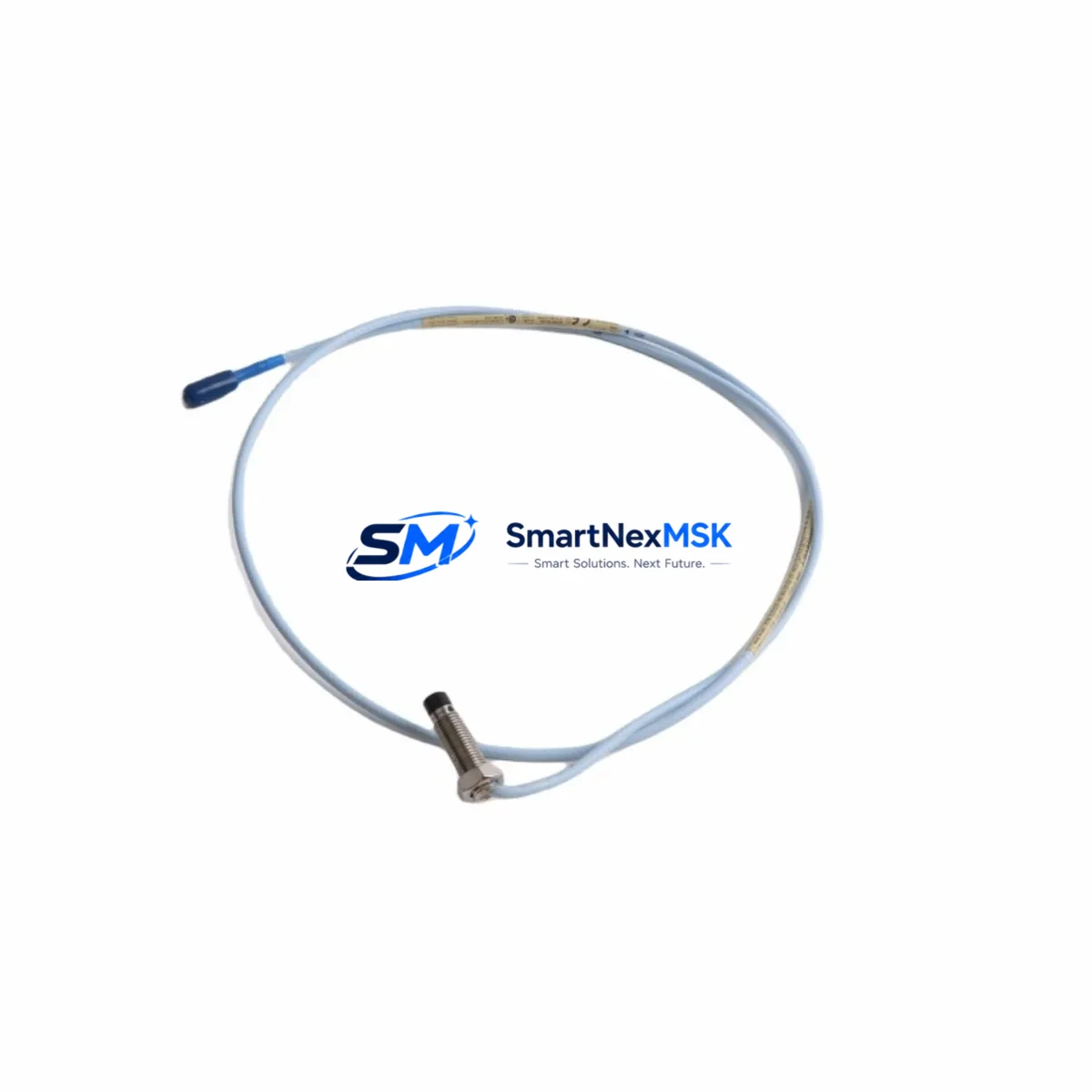
The Bently Nevada 330101-00-35-10-02-00 is an original 8mm proximity transducer engineered for the 3300 XL Proximity Transducer System — one of the most widely deployed vibration and position monitoring platforms in rotating machinery protection. Whether you are managing a planned turnaround, responding to an unplanned trip, or building a critical spare inventory for a compressor train or turbine skid, this transducer delivers the measurement accuracy and system compatibility that maintenance and reliability engineers depend on.
Sourced as an original spare, each unit undergoes pre-shipment functional testing to verify output sensitivity, gap voltage linearity, and cable integrity before dispatch. With a 12-month warranty and documented traceability, this part is suitable for both immediate field replacement and long-term shelf stock in your MRO inventory.
Spare Maintenance Table
| Parameter | Specification |
|---|---|
| Part Number | 330101-00-35-10-02-00 |
| Brand | Bently Nevada |
| Series | 3300 XL Proximity Transducer System |
| Transducer Tip Diameter | 8 mm |
| Cable Length | 3.5 m (integral cable) |
| Extension Cable | 10 m (compatible: 330130 series) |
| Supply Voltage | -24 VDC (nominal) |
| Output Sensitivity | 7.87 V/mm (200 mV/mil) |
| Linear Range | 0.25 – 2.25 mm (10 – 90 mil) |
| Frequency Response | DC to 10,000 Hz |
| Temperature Range | -35°C to +121°C |
| Connector Type | 2-pin MIL-C-5015 (integral) |
| Compatibility | 3300 XL 8mm System; Proximitor® 3300 XL |
| Application | Radial vibration, axial position, differential expansion |
| Condition | Original spare, pre-shipment tested |
| Warranty | 12 months from date of shipment |
| Origin | United States |
Maintenance Planning for Continuous Operation
When a 330101-00-35-10-02-00 proximity transducer is flagged during a routine vibration survey or trips a machinery protection channel, the replacement scope rarely ends with the transducer alone. A disciplined maintenance engineer will use the event as an opportunity to inspect the full measurement loop and adjacent components in the same control cabinet or junction box.
Begin with the Proximitor® sensor (typically a 3300 XL 8mm Proximitor, such as the 330180 series) that conditions the transducer signal. A degraded Proximitor can produce erratic gap voltage readings even with a healthy transducer installed, so both should be verified together. Next, inspect the 330130 series extension cable connecting the transducer to the Proximitor — cable jacket abrasion, connector corrosion, or shield continuity failures are common root causes of intermittent faults that are misdiagnosed as transducer failures.
At the rack level, confirm the 3300/16 or 3500/42 monitor card power supply rails are within specification. A sagging -24 VDC supply will shift the transducer’s operating point and produce false high-vibration alarms. If the site uses a 3500 Series Machinery Protection System, also verify the 3500/20 rack power supply module and its redundant counterpart are both healthy before returning the loop to service.
For plants running older 3300 Series monitors alongside newer 3500 racks, confirm that the Proximitor model and transducer tip size are matched — mixing 5mm and 8mm components in the same loop is a documented source of calibration error. Where the system includes keyphasor transducers (such as the 330980 series), inspect those simultaneously, as keyphasor signal quality directly affects phase-referenced vibration analysis.
In high-temperature or high-vibration environments, also check the armored extension cable conduit fittings, terminal block torque values, and any signal isolators or barriers installed between the Proximitor output and the DCS analog input card. Loose terminals and degraded isolators introduce noise that can mask real machinery faults. Finally, if the machine is approaching a major overhaul interval, consider stocking a matched set of transducer, extension cable, and Proximitor as a complete loop spare — this eliminates compatibility uncertainty during a time-critical shutdown.
Site Replacement Workflow
Step 1 — Isolation and documentation: Before removing the 330101-00-35-10-02-00, record the existing gap voltage (typically -10 to -18 VDC for an 8mm system) and note the alarm and danger setpoints configured in the monitor. This baseline is essential for post-installation verification.
Step 2 — Physical removal: De-energize the Proximitor supply at the rack. Disconnect the extension cable at the junction box, not at the transducer body, to avoid stressing the integral cable. Remove the transducer from the bracket using the correct spanner — avoid gripping the cable.
Step 3 — New transducer installation: Install the replacement 330101-00-35-10-02-00 into the existing bracket. Set the initial gap to the midpoint of the linear range (approximately 1.0–1.25 mm / 40–50 mil) using a non-ferrous feeler gauge or a calibrated gap-setting tool. Reconnect the extension cable and restore Proximitor power.
Step 4 — Gap voltage verification: Measure the Proximitor output voltage. For a correctly gapped 8mm system, the output should read approximately -10.5 to -12.5 VDC at the nominal gap. Adjust the transducer position until the output falls within the monitor’s configured OK range.
Step 5 — Functional test and return to service: Confirm the monitor channel clears the OK relay, verify alarm and danger relay operation if safe to do so, and document the as-left gap voltage in the maintenance record. Update the spare parts log to reflect consumption and initiate a replenishment order to maintain minimum stock levels.
Spare Parts Support FAQ
Q1: Is the 330101-00-35-10-02-00 compatible with both 3300 and 3500 Series monitors?
The 330101-00-35-10-02-00 is designed for the 3300 XL 8mm Proximity Transducer System and is compatible with 3300 XL Proximitors. Compatibility with 3500 Series monitors depends on the specific monitor card and Proximitor pairing — always verify the monitor’s accepted transducer list and confirm the Proximitor model before installation. We recommend providing your full system configuration for a compatibility check prior to ordering.
Q2: What pre-shipment testing is performed on each unit?
Each 330101-00-35-10-02-00 unit is functionally tested before shipment to verify output sensitivity (7.87 V/mm), gap voltage linearity across the full linear range, and integral cable continuity and shield integrity. A test report is available upon request. Units are shipped with protective end caps and anti-static packaging to prevent transit damage.
Q3: What is the recommended spare stock quantity for a critical rotating machine?
For a single critical machine (e.g., a high-speed compressor or steam turbine), a minimum of two transducers per measurement plane is recommended — one installed, one on-shelf. For a train with multiple radial and axial measurement points, a matched set of transducer plus extension cable per channel is best practice. This eliminates the risk of a single-point spare shortage extending an unplanned outage.
Q4: What does the 12-month warranty cover?
The 12-month warranty covers manufacturing defects, output sensitivity out of specification, and integral cable or connector failures under normal operating conditions. It does not cover damage resulting from incorrect installation gap, mechanical impact, or operation outside the rated temperature range. Warranty claims are processed with return of the defective unit and a completed failure description form.
© 2026 SMARTNEXMSK. All rights reserved.
Original Source: https://smartnexmsk.com
Contact: sales@smartnexmsk.com | +86 18259474341


