Bently Nevada 330101-00-40-10-02-00 Spare for 3300 XL Automation
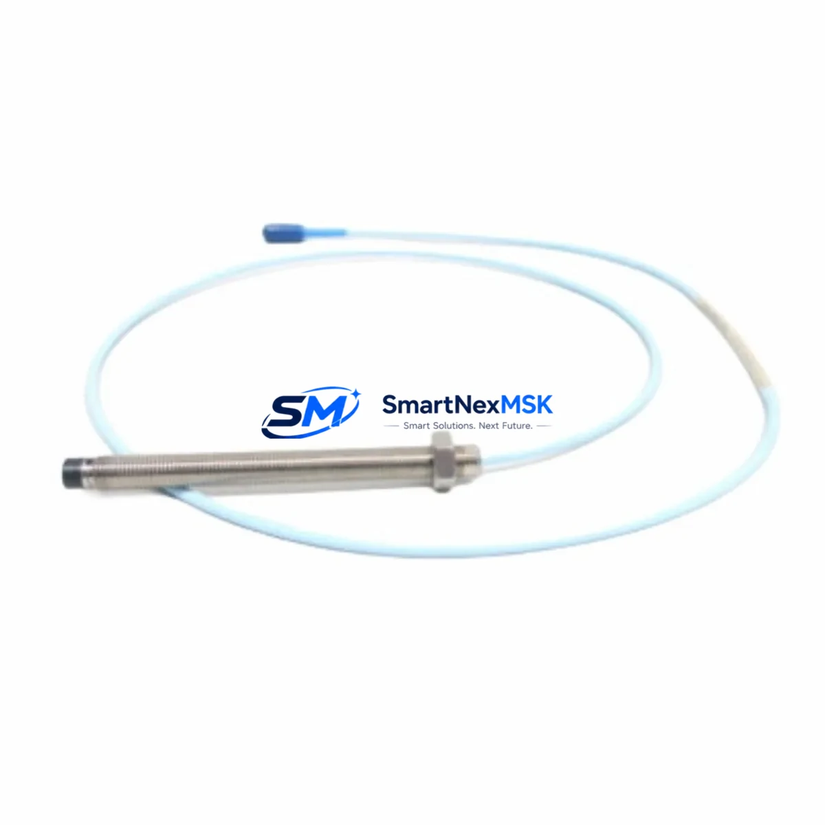
The Bently Nevada 330101-00-40-10-02-00 is an 8mm eddy-current proximity probe engineered for the 3300 XL Series continuous vibration monitoring system. As a maintenance-ready original spare, this probe is a critical component in rotating machinery protection programs across turbines, compressors, pumps, and gearboxes operating in oil & gas, power generation, petrochemical, and heavy industrial environments. When a proximity probe fails or degrades, the entire vibration channel goes blind — exposing rotating assets to undetected shaft displacement, orbit anomalies, and catastrophic bearing failure. Stocking a verified replacement of the 330101-00-40-10-02-00 is a fundamental requirement of any responsible predictive maintenance (PdM) or reliability-centered maintenance (RCM) program.
Spare Maintenance Table
| Part Number | 330101-00-40-10-02-00 |
| Brand | Bently Nevada |
| Series | 3300 XL |
| Probe Type | Eddy-Current Proximity Probe, 8mm |
| Probe Length | 40 cm (400 mm) armored cable |
| Tip Diameter | 8 mm |
| Operating Gap Range | 0.25 mm – 2.25 mm (nominal linear range) |
| Output Sensitivity | 200 mV/mil (7.87 V/mm) nominal |
| Supply Voltage | –24 VDC (via 3300 XL driver/extension cable) |
| Compatible Driver | Bently Nevada 330180 / 330130 Series Proximitor Sensor |
| Compatible Extension Cable | 330130-045-00-00 / 330130-080-00-00 |
| Temperature Range | –35°C to +177°C (probe tip) |
| Target Material | AISI 4140 steel or equivalent ferromagnetic alloy |
| Installation | Threaded mount, 3/8-24 UNF or metric equivalent bracket |
| Application | Radial shaft vibration, axial position, differential expansion |
| Certifications | CE, ATEX (zone-dependent), FM (consult datasheet) |
| Warranty | 12 Months from shipment date |
| Condition | Original, tested before shipment |
Maintenance Planning for Continuous Operation
When a maintenance or reliability engineer schedules replacement of the 330101-00-40-10-02-00 proximity probe, the scope of inspection should extend well beyond the probe tip itself. The 3300 XL measurement chain is a tightly coupled system: probe, extension cable, and Proximitor sensor must all be verified together to restore a calibrated, trustworthy vibration channel.
Begin by inspecting the 330130 Series extension cable — the coaxial link between the probe and the Proximitor. Cable jacket abrasion, connector corrosion, or impedance drift will corrupt the gap voltage output even with a new probe installed. Next, verify the 3300 XL Proximitor Sensor (330180 Series) output voltage at the –24 VDC supply rail; a drifted or failed Proximitor will produce a flat or erratic DC gap signal regardless of probe condition.
At the panel level, confirm that the 3300 XL monitor rack — including the I/O module, power supply module, and relay output card — is operating within specification. A degraded 3300/20 power supply or a faulty 3300/16 relay module can mask true vibration events or generate nuisance trips. If the machine train includes axial position monitoring, the paired 330103 Series thrust probe and its extension cable should be inspected simultaneously, as both channels share the same monitor slot and power rail.
For facilities running integrated control architectures, check the communication interface between the 3300 XL rack and the DCS or PLC — typically via a 3500/92 communication gateway or a Modbus/PROFIBUS interface card. Signal integrity at the fieldbus level is often overlooked during probe replacement but is essential for alarm annunciation and historian data continuity. Where applicable, inspect signal isolators or barriers in the intrinsically safe (IS) circuit to confirm they have not degraded over time.
Finally, review the terminal strip and junction box wiring at the machine skid. Loose terminations, moisture ingress, or corroded ferrules at the field junction box are a common root cause of intermittent gap voltage errors that are incorrectly attributed to probe failure. A complete inspection of the wiring harness, conduit seals, and grounding continuity will prevent repeat failures after the new 330101-00-40-10-02-00 is installed.
Site Replacement Workflow
Step 1 — Isolation & Lockout: Follow site LOTO procedures. De-energize the –24 VDC supply to the affected Proximitor channel at the monitor rack before disconnecting the probe or extension cable.
Step 2 — Gap Voltage Baseline: Before removal, record the existing DC gap voltage from the monitor display or the Proximitor output terminal. This baseline confirms the original installation gap and serves as the reference for the new probe setup.
Step 3 — Probe Removal: Unthread the 330101-00-40-10-02-00 from its mounting bracket. Inspect the probe tip for mechanical damage, pitting, or contamination. Inspect the bracket bore for wear or misalignment that could affect the replacement probe’s gap setting.
Step 4 — Extension Cable Inspection: Disconnect the extension cable at both ends. Perform a continuity and insulation resistance check. Replace the extension cable if resistance is outside the 3300 XL specification (typically 95–105 Ω system resistance at 25°C).
Step 5 — New Probe Installation: Thread the replacement 330101-00-40-10-02-00 into the bracket. Set the probe gap to the manufacturer-specified nominal gap (typically 1.0–1.5 mm for 8mm probes on steel targets). Verify gap voltage at the Proximitor output: target –10.0 VDC ± 0.5 VDC at nominal gap.
Step 6 — System Verification: Re-energize the channel. Confirm gap voltage, vibration baseline, and alarm setpoints in the 3300 XL monitor. Perform a functional test of the relay output and DCS/historian data path before returning the machine to service.
Step 7 — Documentation: Record the replacement date, new gap voltage, probe serial number, and technician sign-off in the equipment maintenance log. Update the spare parts inventory to trigger reorder of the next 330101-00-40-10-02-00 unit.
Spare Parts Support FAQ
Q1: Is the 330101-00-40-10-02-00 compatible with both the 3300 XL and the legacy 3300 Series monitors?
The 330101-00-40-10-02-00 is designed and calibrated for the 3300 XL system. While the physical connector and thread form are similar to some legacy 3300 Series probes, the system resistance and sensitivity calibration are specific to the 3300 XL Proximitor. Always verify system resistance (probe + extension cable) against the Proximitor specification before installation in a legacy rack. We recommend confirming compatibility with your site’s instrument datasheet before ordering.
Q2: What is your recommended spare parts stocking strategy for critical rotating machinery?
For machines classified as critical (no installed spare, continuous operation required), we recommend maintaining a minimum of two 330101-00-40-10-02-00 probes per machine train in the site warehouse, along with one matched extension cable set and one spare Proximitor sensor. For semi-critical machines, one probe per train is the minimum. Spare parts should be stored in original packaging in a climate-controlled environment and rotated on a 3–5 year cycle to prevent connector oxidation and cable jacket degradation.
Q3: How is each unit tested before shipment?
Every 330101-00-40-10-02-00 unit is bench-tested prior to shipment. Testing includes DC gap voltage verification at nominal gap, system resistance measurement, and visual inspection of the probe tip, cable jacket, and connector. A test report is available upon request. Units are shipped in anti-static, padded packaging to prevent transit damage to the probe tip and cable assembly.
Q4: What does the 12-month warranty cover, and what is the claims process?
The 12-month warranty covers manufacturing defects, calibration failures, and premature component failure under normal operating conditions as specified in the Bently Nevada 3300 XL installation manual. The warranty period begins from the shipment date. To initiate a warranty claim, contact our technical support team with the order number, installation date, failure description, and gap voltage readings at the time of failure. Replacement units are dispatched within 3 business days of claim approval. Physical damage, incorrect installation, or operation outside the specified environmental range is not covered.
© 2026 SMARTNEXMSK. All rights reserved.
Original Source: https://smartnexmsk.com
Contact: sales@smartnexmsk.com | +86 18259474341


