Bently Nevada 330101-00-48-20-12-05 Spare for 3300 XL Automation
The Bently Nevada 330101-00-48-20-12-05 is an 8mm proximity transducer engineered for the 3300 XL Series continuous machinery monitoring system. As a maintenance-ready original spare, this unit is sourced, inspected, and tested prior to shipment — ensuring drop-in replacement capability with zero configuration drift. For rotating machinery protection systems where unplanned downtime carries significant operational and financial risk, having a verified spare on the shelf is not optional — it is a core element of any credible maintenance strategy.
Industrial facilities running turbines, compressors, pumps, and gearboxes under continuous monitoring rely on the 3300 XL platform for vibration, position, and speed measurement. When a transducer in this chain degrades or fails, the monitoring loop is broken — triggering either a false trip or, worse, a blind spot in machinery protection. The 330101-00-48-20-12-05 restores that loop with a factory-specification replacement that maintains signal integrity across the full operating range.
Spare Maintenance Table
| Parameter | Specification |
|---|---|
| Part Number | 330101-00-48-20-12-05 |
| Brand | Bently Nevada |
| Series | 3300 XL |
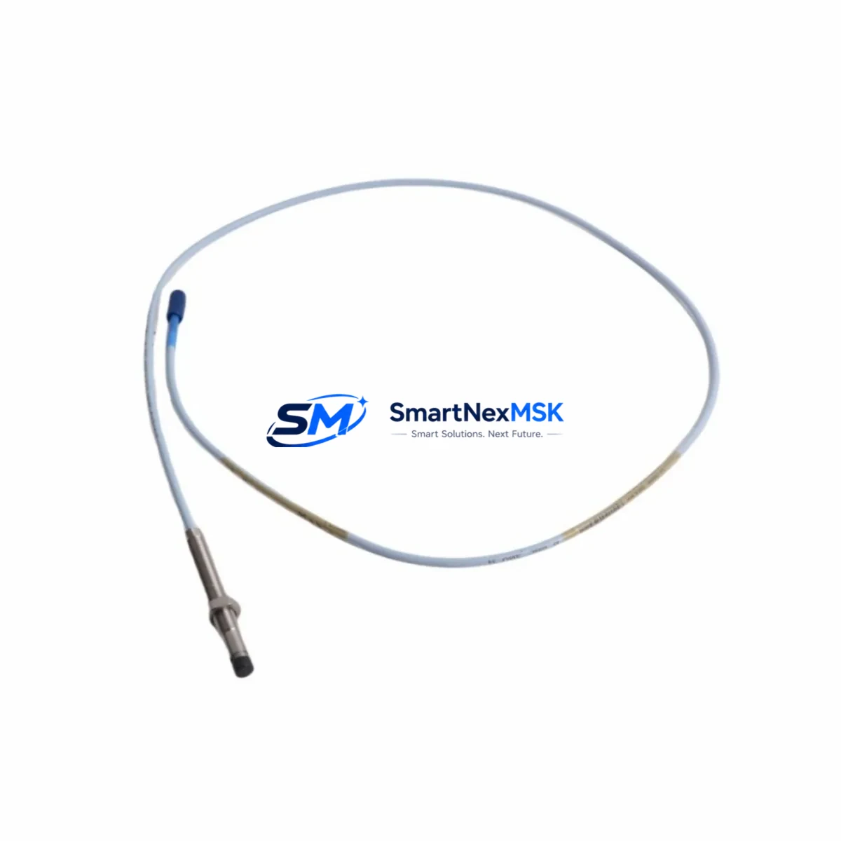
| Type | 8mm Proximity Transducer |
| Probe Length | 48 inches (1219 mm) integral cable |
| Gap Voltage Range | −10 VDC to −18 VDC |
| Scale Factor | 200 mV/mil (7.87 V/mm) |
| Operating Temperature | −35°C to +121°C (probe); −35°C to +66°C (driver) |
| Compatibility | 3300 XL 8mm Proximitor Sensor, 3300 XL Monitoring System |
| Thread | M10 × 1 |
| Connector | 5-pin MIL-C-5015 (integral) |
| Application | Radial vibration, axial position, speed measurement on rotating machinery |
| Installation Environment | Industrial — oil mist, high temperature, high vibration zones |
| Pre-shipment Testing | Yes — functional and gap voltage verified |
| Warranty | 12 Months |
| Origin | USA |
Maintenance Planning for Continuous Operation
Replacing the 330101-00-48-20-12-05 in the field is rarely an isolated task. Maintenance engineers performing a transducer swap on a 3300 XL loop should treat the replacement as an opportunity to audit the entire signal chain. The 3300 XL Proximitor Sensor (driver module, typically 330180 series) should be inspected for output voltage stability and housing integrity — a degraded driver will cause a new transducer to read incorrectly even if the probe itself is healthy.
The extension cable connecting the probe to the Proximitor (commonly 330130 series armored cable) is a frequent failure point in high-vibration environments. Inspect for jacket cracking, connector corrosion, and continuity. A compromised cable introduces noise into the vibration signal and can cause nuisance trips or mask real machinery faults.
At the rack level, verify the 3300 XL Monitor module (such as the 3300/16 or 3300/20 series) for alarm setpoint integrity and I/O card seating. Loose backplane connections in the 3300 XL Rack can cause intermittent signal loss that mimics transducer failure. While the rack is open, inspect the power supply module (e.g., 3300/05 or equivalent) for output voltage within specification — an under-voltage condition will shift the transducer’s operating point and corrupt gap measurements.
For facilities running parallel monitoring on critical trains, the 3500 Series Monitoring System components — including 3500/42M Proximitor I/O modules and 3500/15 Power Supply — may share the same control cabinet. These should be checked for firmware currency and relay output integrity during the same maintenance window.
If the machinery train also uses Keyphasor transducers (e.g., 330980 series) for phase reference, confirm that the Keyphasor signal is clean and properly gapped. A degraded Keyphasor will corrupt all phase-referenced vibration data across the monitoring system. Additionally, inspect any signal conditioners or isolators in the loop — particularly if the 3300 XL output feeds a DCS historian or safety system — to ensure 4–20 mA or voltage outputs remain within calibrated range.
Terminal blocks and field wiring terminations in the junction box should be torqued to specification and inspected for oxidation, especially in humid or chemically aggressive environments. Loose terminations are a leading cause of intermittent faults that are difficult to diagnose remotely.
Site Replacement Workflow
Step 1 — Verify compatibility before removal. Confirm the replacement 330101-00-48-20-12-05 matches the installed probe length, thread size, and connector type. Cross-reference the system documentation or the label on the existing Proximitor driver to confirm the 8mm system designation.
Step 2 — De-energize and isolate. Follow site LOTO procedures. Remove power from the Proximitor driver before disconnecting the probe. Note the existing gap voltage reading from the monitor display or DCS historian before shutdown — this serves as a baseline for post-installation verification.
Step 3 — Remove the old transducer. Unthread the probe from the bracket. Inspect the target area (shaft or thrust collar) for surface damage, scoring, or runout that may have contributed to the original failure. Document findings.
Step 4 — Install the replacement. Thread the new 330101-00-48-20-12-05 into the bracket. Set the initial gap to the manufacturer-recommended starting point (typically 1.0–1.5 mm for 8mm probes). Connect the extension cable and Proximitor driver.
Step 5 — Re-energize and verify gap voltage. Power up the Proximitor and read the output voltage. Adjust the probe gap until the gap voltage falls within the linear range (typically −10 to −18 VDC). Fine-tune to match the pre-removal baseline where possible.
Step 6 — Functional check and alarm verification. Confirm the monitor module is receiving a valid signal. Verify that vibration, position, or speed readings are within expected ranges for the machinery at rest and during startup. Check that alarm and trip setpoints are active and correctly configured.
Step 7 — Document and return to service. Record the replacement in the maintenance management system (CMMS), including the new part serial number, gap voltage setting, and post-installation readings. Update the spare parts inventory to trigger reorder of a replacement unit.
Spare Parts Support FAQ
Q: Is the 330101-00-48-20-12-05 a direct drop-in replacement for the original installed unit?
A: Yes, provided the replacement matches the probe length, thread specification, and connector type of the installed unit. The 330101-00-48-20-12-05 is an 8mm proximity transducer with a 48-inch integral cable and M10 × 1 thread, designed for direct installation into 3300 XL system brackets without modification.
Q: What pre-shipment testing is performed on this spare?
A: Each unit undergoes functional verification including gap voltage output check and continuity testing of the integral cable and connector before shipment. A test report is available upon request. The 12-month warranty covers defects in materials and workmanship from the date of shipment.
Q: How should this spare be stored to maintain readiness?
A: Store in the original packaging or an ESD-safe enclosure in a dry, temperature-controlled environment (10°C to 40°C). Avoid exposure to strong magnetic fields, solvents, or mechanical shock. Inspect the connector and cable jacket annually if the spare is held in long-term storage.
Q: Can this transducer be used with the Bently Nevada 3500 Series monitoring system?
A: The 330101-00-48-20-12-05 is designed and rated for the 3300 XL 8mm system. Compatibility with 3500 Series I/O modules depends on the specific Proximitor driver and rack configuration. Consult the 3500 system documentation or contact our technical team to confirm compatibility before installation in a 3500 Series application.
© 2026 SMARTNEXMSK. All rights reserved.
Original Source: https://smartnexmsk.com
Contact: sales@smartnexmsk.com | +86 18259474341


