Bently Nevada 330101-00-61-15-12-05 Spare 3300 XL: Precision Replacement for Industrial Downtime Control
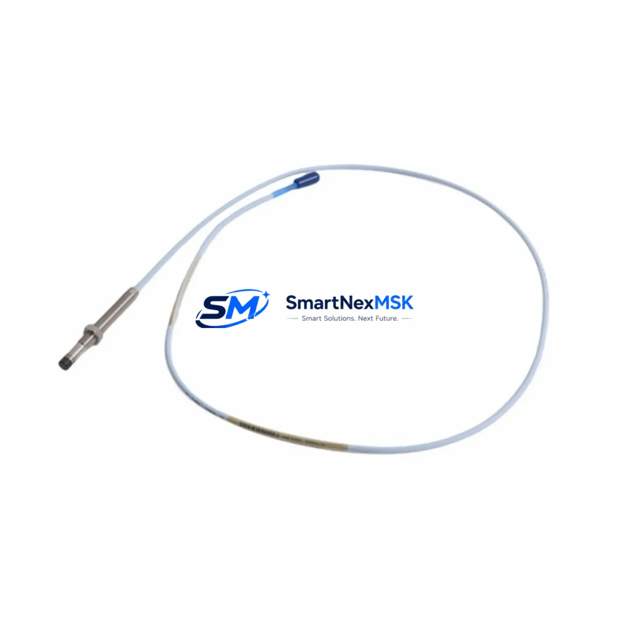
The Bently Nevada 330101-00-61-15-12-05 is an 8mm proximity transducer engineered for the 3300 XL Series continuous machinery monitoring system. As a maintenance-ready original spare, it is designed to deliver immediate drop-in replacement capability for rotating machinery protection applications — including turbines, compressors, pumps, and gearboxes — where unplanned downtime carries significant operational and financial risk. Every unit shipped by SMARTNEXMSK is sourced from verified supply channels, function-tested prior to dispatch, and backed by a 12-month warranty covering manufacturing defects and performance conformance.
For maintenance engineers managing critical rotating assets, the 330101-00-61-15-12-05 transducer is a cornerstone spare. Its eddy-current sensing principle provides non-contact, continuous shaft displacement and vibration measurement, feeding real-time data to the 3300 XL monitor rack. When this transducer degrades or fails — whether due to cable damage, connector corrosion, tip contamination, or gap drift — the entire vibration channel goes blind, triggering nuisance trips or, worse, masking genuine machinery faults. Stocking this part as a ready-to-install spare is a fundamental element of any reliability-centered maintenance (RCM) program for rotating equipment.
Spare Maintenance Table
| Parameter | Specification / Detail |
|---|---|
| Part Number | 330101-00-61-15-12-05 |
| Brand | Bently Nevada |
| Series | 3300 XL |
| Type | 8mm Proximity Transducer (Eddy-Current) |
| Sensing Range | 0–2.54 mm (0–100 mil) linear range |
| Output Sensitivity | 7.87 V/mm (200 mV/mil) |
| Supply Voltage | –24 VDC (nominal), via 3300 XL Proximitor® driver |
| Cable Length | 5m (extension cable dependent on system configuration) |
| Connector Type | MIL-C-5015 style, compatible with 3300 XL Proximitor® Series |
| Target Material Compatibility | AISI 4140 steel (standard); verify for non-ferrous shafts |
| Operating Temperature | –35°C to +121°C (transducer body) |
| Environmental Rating | IP67 (connector end sealed) |
| Compatible Monitor | Bently Nevada 3300 XL Series, 3500 Series (with adapter) |
| Application | Radial vibration, axial position, differential expansion |
| Mounting Thread | M10 × 1.0 (standard bracket mount) |
| Origin | USA |
| Condition | Original spare, new-in-box or refurbished-tested (state on order) |
| Warranty | 12 Months — covers manufacturing defects and performance conformance |
| Lead Time | In-stock: ships within 1–3 business days; ETA confirmed at order |
Maintenance Planning for Continuous Operation
Replacing the 330101-00-61-15-12-05 transducer in the field is rarely an isolated task. A disciplined maintenance engineer will treat the transducer swap as an opportunity to inspect and verify the entire vibration measurement chain. The 3300 XL Proximitor® sensor driver (typically the 330180 or 330130 series) should be checked for output voltage stability and gap voltage within the –10 V to –18 V window before the new transducer is installed. If the Proximitor® is out of calibration or showing erratic output, replacing the transducer alone will not restore channel integrity.
The extension cable assembly — commonly the 330130-080-00-00 or equivalent armored cable — must be inspected for jacket damage, connector pin corrosion, and continuity. A degraded cable introduces impedance errors that shift the transducer’s linear range and produce false vibration readings. Similarly, the junction box terminal blocks and cable gland seals at the machinery skid should be checked for moisture ingress, especially in outdoor or wash-down environments.
At the monitor rack level, the 3300 XL monitor card (e.g., 3300/16 or 3300/20 series) should be reseated and its OK relay output verified after transducer replacement. If the plant uses a 3500 Series rack for newer machinery, confirm that the correct I/O module and transducer interface card are installed, as the 3300 XL and 3500 systems use different backplane communication protocols. The 3500/42M Proximitor®/Seismic Monitor is a common companion module in mixed-generation installations.
For plants running DCS integration via 4–20 mA or HART output from the monitor rack, verify that the analog output scaling matches the DCS input card range after replacement. A misconfigured signal isolator or barrier module (such as a Pepperl+Fuchs or MTL Zener barrier in hazardous-area installations) can clip the vibration signal and mask high-vibration alarms. Check the intrinsic safety barrier entity parameters against the transducer’s capacitance and inductance specifications if the installation is in a Zone 1 or Division 1 classified area.
During planned outages, it is also advisable to inspect the keyphasor transducer (e.g., 330980 series) mounted on the same shaft, as keyphasor signal quality directly affects phase-referenced vibration analysis. A worn or contaminated keyphasor notch will degrade balancing and diagnostic accuracy even after the radial transducer is replaced. Finally, review the rack power supply module (e.g., 3500/15 Power Supply) for output ripple and voltage stability — an unstable supply rail is a common root cause of intermittent transducer faults that are misdiagnosed as transducer failures.
Site Replacement Workflow
Step 1 — Pre-replacement verification: Record the existing gap voltage (target: –10 V to –18 V DC) using a calibrated multimeter at the Proximitor® output terminals. Document the as-found vibration reading and alarm setpoints from the 3300 XL monitor display or DCS historian.
Step 2 — Safe isolation: Follow site LOTO (Lockout/Tagout) procedures. De-energize the Proximitor® driver by disconnecting the –24 VDC supply at the rack terminal. Do not cut power to the entire monitor rack if other channels are in service — the 3300 XL supports per-channel isolation.
Step 3 — Transducer removal: Unscrew the transducer from the mounting bracket using the correct spanner (avoid pipe wrenches that can damage the body). Disconnect the Proximitor® cable at the junction box. Inspect the mounting bracket threads and replace if corroded.
Step 4 — New transducer installation: Install the 330101-00-61-15-12-05 into the bracket. Set the air gap to the manufacturer-specified value (typically 1.0–1.5 mm for 8mm probes on AISI 4140 targets) using a feeler gauge. Reconnect the Proximitor® cable and restore –24 VDC supply.
Step 5 — Gap voltage verification: Confirm gap voltage is within –10 V to –18 V DC. Adjust gap if necessary. Verify the monitor OK relay is energized and the channel is in normal (non-alarm) state.
Step 6 — Functional test: Perform a slow-roll check or bump test to confirm the transducer is responding to shaft motion. Compare readings against historical baseline. Update the maintenance record with as-left gap voltage, date, and technician ID.
This workflow minimizes restart risk and ensures the replacement transducer is performing within specification before the machine is returned to service — reducing the probability of a repeat trip event within the first 72 hours of operation.
Spare Parts Support FAQ
Q1: Is the 330101-00-61-15-12-05 compatible with both 3300 XL and 3500 Series monitors?
The 330101-00-61-15-12-05 is natively designed for the 3300 XL Series. It can be used with 3500 Series monitors when paired with the correct Proximitor® driver and interface module. Always verify the system’s transducer input specifications and confirm the gap voltage range matches before installation in a 3500 rack.
Q2: What is your inventory policy for long-term spare parts supply?
SMARTNEXMSK maintains buffer stock of high-demand Bently Nevada 3300 XL series components to support both emergency replacement and planned maintenance schedules. For customers requiring guaranteed availability over a 12–36 month horizon, we offer blanket order arrangements with reserved stock allocation. Contact sales@smartnexmsk.com to discuss your site’s spare parts strategy.
Q3: How is each unit tested before shipment?
Every 330101-00-61-15-12-05 unit undergoes pre-shipment functional verification including gap voltage output check, cable continuity test, and connector integrity inspection. Units are packaged in anti-static, shock-protected packaging with a test record included. New-in-box units are shipped in original manufacturer packaging where available.
Q4: What does the 12-month warranty cover?
The 12-month warranty covers manufacturing defects, performance non-conformance to published specifications, and connector/cable assembly failures under normal operating conditions. It does not cover damage resulting from incorrect installation, gap setting errors, overvoltage, or mechanical impact. Warranty claims are processed within 5 business days of receipt of the returned unit, with replacement or credit issued upon verification.
© 2026 SMARTNEXMSK. All rights reserved.
Original Source: https://smartnexmsk.com
Contact: sales@smartnexmsk.com | +86 18259474341


