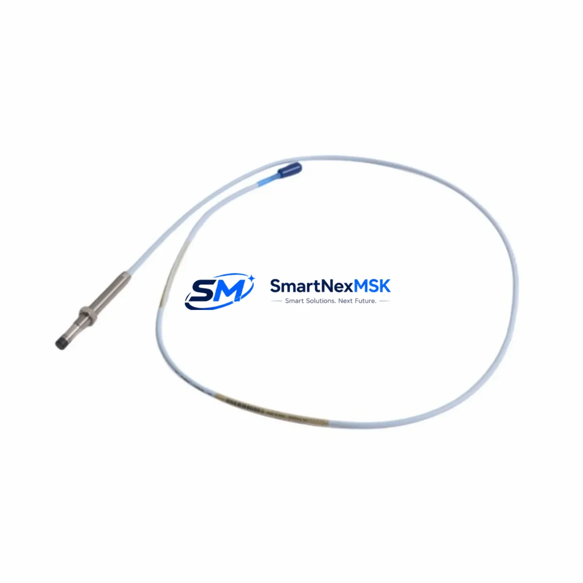
Bently Nevada 330101-00-67-20-02-05 Retrofit-Ready Proximity Probe for 3300 XL Control Systems
The Bently Nevada 330101-00-67-20-02-05 is an 8mm eddy-current proximity probe engineered for seamless integration into legacy 3300 XL vibration monitoring systems. As original equipment reaches end-of-life and OEM spare parts become increasingly difficult to source, this retrofit-ready probe provides a verified drop-in replacement path that preserves existing wiring, signal conditioning infrastructure, and machinery protection logic without requiring a full system overhaul.
Industrial facilities operating rotating machinery — including steam turbines, gas compressors, centrifugal pumps, and large electric motors — rely on continuous shaft displacement monitoring to prevent catastrophic bearing failures. The 330101-00-67-20-02-05 maintains the same 8mm tip diameter, -24 VDC bias voltage, and 200 mV/mil (7.87 V/mm) sensitivity as the original Bently Nevada specification, ensuring that existing Proximitor® sensor modules such as the 3300 XL 8mm Proximitor® (3300/16) continue to operate within calibrated parameters after probe replacement.
Before installation, engineers should confirm power supply capacity at the junction box, verify that the existing extension cable — typically a 3300 XL armored extension cable in 5m or 9m lengths — is undamaged and properly terminated, and check that the Proximitor® output signal falls within the linear range of -4 VDC to -18 VDC at the expected gap distance. The probe tip-to-target gap should be set to the manufacturer-recommended 1.0 mm (approximately -10.4 VDC output) using a calibrated gap tool before the machine is returned to service.
For facilities migrating from older 3300 series hardware to the current 3500 Series Machinery Protection System, the 330101-00-67-20-02-05 remains compatible with 3500/42M Proximitor®/Seismic Monitor modules when used with the appropriate 3500 series I/O module and rack configuration. This compatibility simplifies phased migration strategies where probe infrastructure is retained while the monitoring rack, power supply module, and communication gateway are upgraded incrementally.
Upgrade Compatibility Table
| Parameter | 330101-00-67-20-02-05 (This Unit) | Notes / Retrofit Guidance |
|---|---|---|
| Probe Diameter | 8 mm | Matches standard 3300 XL 8mm probe bore; no re-machining required |
| Sensitivity | 200 mV/mil (7.87 V/mm) | Calibrated to 3300/16 Proximitor® — verify output at nominal gap before restart |
| Bias Voltage | -24 VDC nominal | Confirm Proximitor® supply rail; replace 3300 XL power supply if voltage is marginal |
| Cable Length | Probe: 0.5 m integral | Pair with 3300 XL 5m or 9m extension cable; inspect connector pins before mating |
| Target Material | AISI 4140 steel (recommended) | Verify shaft material; non-magnetic alloys require recalibration |
| Mounting Thread | 3/8-24 UNF | Use supplied jam nut; torque to 20 in-lb; apply thread-locking compound |
| 3500 Series Compatibility | Compatible with 3500/42M | Requires 3500 series I/O module; update rack configuration in System 1 software |
| Communication Protocol | Analog (4–20 mA / voltage) | For Modbus or Ethernet/IP integration, add 3500/92 Communication Gateway |
| Commissioning Check | Gap voltage, linearity, noise floor | Use Bently Nevada calibration fixture or equivalent signal simulator |
| Warranty | 12 Months | Covers manufacturing defects; includes pre-shipment functional test report |
Retrofit Planning for Existing Automation Systems
A successful retrofit begins well before the maintenance window opens. The 330101-00-67-20-02-05 is most commonly deployed in control cabinets alongside the 3300/16 Proximitor® sensor, a dedicated 3300 XL power supply module, and a 3300/55 Keyphasor® module that provides once-per-revolution reference signals for phase analysis. When planning the replacement, the maintenance team should document the current Proximitor® output voltage at the installed gap, photograph the existing terminal block wiring, and record the channel address assigned in the monitoring rack before any hardware is disturbed.
Facilities that have already partially migrated to the 3500 Series platform will find that the 330101-00-67-20-02-05 integrates directly with the 3500/42M monitor card without probe-side modifications. The 3500 rack’s I/O module accepts the same terminal wiring convention as the legacy 3300 XL barrier strip, reducing re-wiring time significantly. Where the control system communicates upstream to a DCS or SCADA platform via a 3500/92 Communication Gateway, engineers should verify that the new probe channel is correctly mapped in the gateway’s Modbus register table and that the DCS historian — whether running on a Honeywell Experion PKS, Emerson DeltaV, or Yokogawa CENTUM VP platform — receives updated tag descriptors before the machine is restarted.
I/O expansion during the same outage window is a common efficiency measure. If the facility is adding radial vibration channels for a previously unmonitored bearing, a 3500/40M Proximitor®/Seismic Monitor or an additional 3300 XL monitor card can be installed in the same rack, sharing the existing power supply if capacity permits. The 330101-00-67-20-02-05 probe, extension cable, and Proximitor® assembly should be bench-tested as a matched set before installation to confirm sensitivity and linearity, reducing the risk of a failed commissioning check during a time-critical outage.
For facilities still operating on the original 3300 Series (non-XL) platform, the migration path typically involves replacing the monitor rack with a 3500 Series chassis, retaining the existing probe and extension cable infrastructure where cable condition permits, and updating the System 1 machinery management software configuration to reflect the new rack topology. The 330101-00-67-20-02-05 is fully compatible with this migration path and has been pre-shipment tested to confirm output linearity across the full gap range.
Downtime Control During System Migration
Minimizing unplanned downtime is the primary concern for any rotating machinery protection upgrade. The recommended approach is to complete all pre-installation work — including bench calibration of the 330101-00-67-20-02-05 probe assembly, verification of the Proximitor® supply voltage, and review of the existing PLC or DCS program logic for any hardcoded gap alarm setpoints — before the machine is taken offline.
During the maintenance window, the original probe should be removed carefully, the probe bore cleaned and inspected for wear, and the new probe installed and gapped before any other work proceeds. This sequence ensures that the vibration monitoring channel is restored to service as quickly as possible, allowing the machine to be restarted under full protection while other maintenance tasks — such as bearing inspection, seal replacement, or coupling alignment — are completed in parallel.
Where the control system uses a redundant monitoring architecture, the replacement can often be performed on one channel at a time while the redundant channel remains active, eliminating the need for a full protection bypass. Engineers should confirm with the site safety officer whether a temporary bypass is required and ensure that the bypass is logged, time-limited, and cleared before the machine returns to normal operation. Original program logic, HMI faceplate configurations, and alarm setpoints should be backed up before any rack or gateway firmware is updated, and the backup should be verified restorable before the outage begins.
Retrofit Support FAQ
Q: Is the 330101-00-67-20-02-05 a direct drop-in replacement for the original Bently Nevada probe in my 3300 XL system?
A: Yes. The 330101-00-67-20-02-05 matches the original 8mm diameter, sensitivity, bias voltage, and thread specification. No modifications to the probe bore, extension cable, or Proximitor® module are required. A gap re-check and output voltage verification are recommended after installation.
Q: Can this probe be used with the 3500 Series Machinery Protection System?
A: Yes. The 330101-00-67-20-02-05 is compatible with the 3500/42M Proximitor®/Seismic Monitor when used with the appropriate 3500 series I/O module. Update the rack configuration in System 1 software and verify channel mapping in the communication gateway before restarting the machine.
Q: What commissioning checks are required after installation?
A: Set the probe gap to 1.0 mm and confirm the Proximitor® output is approximately -10.4 VDC. Verify the output voltage at minimum and maximum gap limits to confirm linearity. Check the noise floor with the machine stationary before startup. Confirm that DCS and HMI alarm setpoints reflect the calibrated gap voltage.
Q: What does the 12-month warranty cover, and is a test report included?
A: The 12-month warranty covers manufacturing defects in materials and workmanship from the date of shipment. Each unit ships with a pre-shipment functional test report confirming sensitivity, linearity, and output voltage at nominal gap. Warranty claims are processed through SMARTNEXMSK with a typical response time of 2 business days.
© 2026 SMARTNEXMSK. All rights reserved.
Original Source: https://smartnexmsk.com
Contact: sales@smartnexmsk.com | +86 18259474341


