Bently Nevada 330101-00-70-10-02-00 Spare 3300 XL Automation
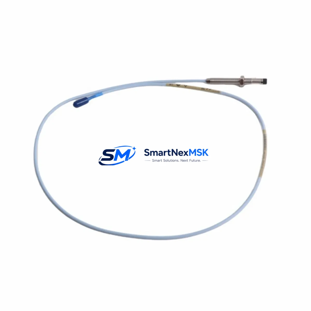
The Bently Nevada 330101-00-70-10-02-00 is an original 8mm eddy-current proximity transducer engineered for the 3300 XL Series continuous vibration monitoring system. In rotating machinery protection environments — turbines, compressors, pumps, and gearboxes — this transducer serves as the primary sensing element for radial shaft vibration, axial position, and differential expansion measurement. When this component fails or degrades, the entire protection loop is compromised, exposing critical assets to undetected mechanical faults and unplanned downtime.
Sourced as a genuine original spare, the 330101-00-70-10-02-00 is tested prior to shipment and backed by a 12-month warranty. Stocking this transducer as a ready-to-deploy spare is the single most effective step a maintenance team can take to reduce mean time to repair (MTTR) on vibration-monitored machinery.
Spare Maintenance Table
| Parameter | Specification |
|---|---|
| Part Number | 330101-00-70-10-02-00 |
| Brand | Bently Nevada |
| Series | 3300 XL |
| Transducer Type | 8mm Eddy-Current Proximity |
| Measurement | Radial Vibration, Axial Position, Differential Expansion |
| Output Range | -18 VDC nominal (200 mV/mil, 7.87 V/mm) |
| Operating Temperature | -35°C to +177°C |
| Cable Length | 5m (standard; specify at order) |
| Connector | 3-pin MIL-C-5015 style |
| Compatible Driver/Monitor | 3300 XL 8mm Proximitor Sensor, 3500 Series Monitors |
| Target Material | AISI 4140 steel or equivalent |
| Installation | Threaded probe tip, locknut secured |
| Application Environment | Turbines, Compressors, Pumps, Gearboxes |
| Maintenance Recommendation | Replace at first sign of signal drift, gap voltage anomaly, or physical cable damage |
| Warranty | 12 Months |
| Condition | Original, Pre-shipment Tested |
Maintenance Planning for Continuous Operation
When a maintenance or reliability engineer schedules replacement of the 330101-00-70-10-02-00 transducer, the scope of inspection should extend beyond the probe itself. The 3300 XL measurement chain is a tightly coupled system: a fault in any upstream or downstream component will produce the same symptom — erratic or lost vibration signal — making root-cause isolation difficult without a structured checklist.
Begin with the 3300 XL 8mm Proximitor Sensor (driver module), which conditions the transducer signal and provides the -24 VDC bias supply. A failed or drifting Proximitor will produce gap voltage readings outside the -2 VDC to -18 VDC linear range even with a healthy transducer installed. Inspect the extension cable assembly (typically 3300 XL armored extension cable, 5m or 9m) for continuity, insulation resistance, and connector pin integrity — cable damage is the most common cause of intermittent transducer faults in high-vibration environments.
At the 3500 Series rack monitor level, verify that the I/O module assigned to this channel is seated correctly and that the channel configuration (gap, direct, 1X/2X) matches the replacement transducer’s sensitivity. Check the 3500/42M Proximitor I/O Module or equivalent for any blown protection fuses or relay contact wear on the alarm output circuit. If the machine is also equipped with a 3300 XL Velomitor for seismic casing vibration, inspect that sensor simultaneously — both sensors share the same control cabinet wiring tray and are subject to the same environmental stressors.
On the power supply side, confirm that the 3500/15 Power Supply Module is delivering stable -24 VDC to the Proximitor rail. Voltage sag under load is a known cause of false high-vibration trips. For installations using a Bently Nevada 3500/20 Rack Interface Module for Modbus or Ethernet communication, verify that the communication link to the DCS or SCADA is intact after the transducer swap — some firmware versions require a channel reset to re-establish data streaming.
In the field junction box, inspect terminal blocks (Phoenix Contact or equivalent) for corrosion, loose ferrules, and correct torque. Corroded terminals are a leading cause of signal noise that mimics transducer failure. If the installation includes signal isolators between the Proximitor output and the DCS analog input card, verify isolator output voltage and confirm the isolation barrier has not been compromised by moisture ingress.
Finally, for older systems approaching end-of-life, consider stocking the 330130-080-00-00 extension cable and a spare 330180-X1-05 Proximitor Sensor alongside the 330101-00-70-10-02-00 transducer. A three-component spare kit covering probe, cable, and driver eliminates the most common single points of failure in the 3300 XL measurement loop and supports a sub-30-minute field swap.
Site Replacement Workflow
Step 1 — Pre-replacement verification: Record the existing gap voltage (target: -10.0 VDC ±0.5 VDC for a 1.0mm air gap on AISI 4140 steel). Document the current vibration baseline from the 3500 monitor display or historian trend.
Step 2 — Safe isolation: Coordinate with operations to place the machine in a safe state. Do not disconnect the transducer under live bias voltage without confirming the monitor channel is in bypass or the rack is in maintenance mode to prevent spurious trips.
Step 3 — Physical replacement: Remove the locknut and unthread the probe from the bracket. Install the 330101-00-70-10-02-00 replacement, setting the air gap per the original calibration sheet (typically 1.0mm ±0.05mm). Reconnect the extension cable and verify connector seating.
Step 4 — Electrical verification: With bias voltage restored, measure gap voltage at the Proximitor output terminals. Confirm the reading falls within the linear range. If gap voltage is outside specification, re-adjust the probe gap before returning the channel to service.
Step 5 — Functional test: Return the monitor channel to normal operation. Verify that the vibration reading is stable and consistent with the pre-replacement baseline. Confirm alarm and trip setpoints are active. Log the replacement in the CMMS with the new transducer serial number and installation date.
This workflow supports a complete transducer swap in under 45 minutes for a prepared maintenance team, minimizing production impact and ensuring the protection system is fully functional before the machine is returned to service.
Spare Parts Support FAQ
Q: Is the 330101-00-70-10-02-00 compatible with both 3300 XL and 3500 Series monitors?
A: Yes. The 330101-00-70-10-02-00 8mm proximity transducer is designed for use with the 3300 XL Proximitor Sensor driver and is fully compatible with 3500 Series rack monitors when paired with the appropriate I/O module. Always verify channel configuration in the 3500 rack software after installation.
Q: What is the recommended spare parts stocking strategy for this transducer?
A: For critical rotating machinery, maintain a minimum of one spare 330101-00-70-10-02-00 transducer per monitored machine, plus one spare extension cable and one spare Proximitor Sensor driver per monitoring loop. For plants with five or more monitored machines, a pooled inventory of three transducers is a common industry practice to cover simultaneous failures during a major outage.
Q: How is the replacement unit tested before shipment?
A: Each 330101-00-70-10-02-00 unit is bench-tested for gap voltage linearity, sensitivity (200 mV/mil), and cable continuity prior to shipment. A test report is available upon request. Units are shipped in anti-static, padded packaging to prevent transit damage.
Q: What does the 12-month warranty cover?
A: The 12-month warranty covers manufacturing defects, electrical failure under normal operating conditions, and out-of-specification sensitivity. It does not cover physical damage from improper installation, over-range mechanical shock, or chemical exposure beyond the rated operating environment. Warranty claims are processed with return shipment support.
© 2026 SMARTNEXMSK. All rights reserved.
Original Source: https://smartnexmsk.com
Contact: sales@smartnexmsk.com | +86 18259474341


