Bently Nevada 330101-00-72-10-12-05: Retrofit-Ready Proximity Probe for 3300 XL Control Systems
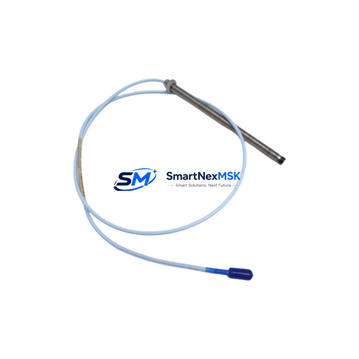
The Bently Nevada 330101-00-72-10-12-05 is an 8mm eddy current proximity probe engineered for the 3300 XL Series continuous machinery monitoring platform. As legacy vibration monitoring systems age and OEM support windows close, this probe remains one of the most critical retrofit components for facilities operating turbines, compressors, pumps, and rotating machinery across oil & gas, power generation, and petrochemical industries. Whether you are replacing a failed unit on an emergency basis, upgrading an aging 3300 Series rack to the 3300 XL standard, or consolidating spare parts inventory ahead of a planned outage, the 330101-00-72-10-12-05 delivers the dimensional accuracy, gap voltage linearity, and signal integrity required for uninterrupted condition monitoring.
Upgrade Compatibility Table
| Parameter | Detail |
|---|---|
| SKU / Part Number | 330101-00-72-10-12-05 |
| Series Compatibility | Bently Nevada 3300 XL Series |
| Probe Diameter | 8mm |
| Cable Length | 72 inches (integral) |
| Extension Cable | 330130 series (5m / 9m options) |
| Driver / Proximitor | 3300 XL 8mm Proximitor (330180 series) |
| Signal Output | –24 VDC nominal gap voltage, linear range 0–80 mil |
| Installation Interface | M10 x 1.0 threaded tip, jam-nut mount |
| Connector Type | Integral coaxial, mates with 330130 extension |
| Replacement for Legacy SKU | 330101-00-72-10-12-00 (prior revision) |
| Rack / Backplane Compatibility | 3300/16 and 3300/20 rack chassis |
| Communication Protocol | Analog 4–20 mA / direct Proximitor output to 3500 rack via I/O module |
| Commissioning Requirement | Gap voltage verification at 50 mil nominal; Keyphasor® reference alignment if applicable |
| Warranty | 12 months from date of shipment |
Retrofit Planning for Existing Automation Systems
Replacing the 330101-00-72-10-12-05 in an operating plant requires a structured approach that accounts for the full measurement chain. The probe does not operate in isolation — it forms a three-component system with the 330130 series extension cable and the 330180 XL 8mm Proximitor module. Before pulling the failed probe, technicians should verify that the Proximitor is outputting a stable –24 VDC supply and that the extension cable connector shows no signs of moisture ingress or mechanical damage. A faulty extension cable is frequently misdiagnosed as a probe failure, so resistance and capacitance checks on the 330130 cable should be completed before ordering a replacement probe.
For facilities migrating from the older 3300 Series (non-XL) to the 3300 XL platform, the probe mounting thread and tip geometry are identical, which simplifies the mechanical retrofit. However, the Proximitor must be upgraded from the legacy 330100 Proximitor to the 330180 XL Proximitor to maintain calibration accuracy. The 3300 XL rack accepts both the 3300/16-channel and 3300/20-channel I/O modules, and the channel assignment in the System 1 or System 1 Evolution software database must be updated to reflect the new probe serial number and calibration coefficients.
In control cabinet upgrades where the 3300 XL rack is being installed alongside a 3500 Series rack for expanded monitoring, the analog output from the Proximitor can be wired directly into the 3500/42M Proximitor I/O module, enabling seamless integration without signal conditioning hardware. Facilities running Modbus RTU or FOUNDATION Fieldbus communication to a DCS should verify that the 3500 rack’s communication gateway — typically the 3500/92 Communication Gateway module — is configured to map the new channel address correctly before the probe is energized.
For I/O expansion projects where additional radial vibration, axial position, or speed measurement points are being added to an existing rack, the 330101-00-72-10-12-05 is commonly deployed alongside 330905 Keyphasor probes for phase reference, 330400 series velocity transducers for bearing housing measurements, and 330500 series displacement probes for thrust position monitoring. Each new measurement point requires a dedicated Proximitor slot in the rack, and the rack power supply — typically the 3300 Power Supply module — should be load-checked to confirm sufficient current capacity before adding channels.
HMI screens connected to the monitoring system via OPC-DA or OPC-UA should be reviewed after probe replacement to confirm that the channel tag name, engineering unit scaling, and alarm setpoints are correctly mapped. In plants using GE Proficy iFIX, Wonderware InTouch, or Emerson DeltaV as the SCADA/HMI layer, a forced-value test on the new channel is recommended before returning the machine to service.
Downtime Control During System Migration
Minimizing unplanned downtime during a proximity probe replacement begins with pre-staging. Before the maintenance window opens, confirm that the replacement 330101-00-72-10-12-05 has been bench-tested for gap voltage linearity across the full 0–80 mil range, that the integral cable connector is undamaged, and that the jam-nut and mounting hardware are on hand. A pre-cut probe installation template matching the machine’s bearing housing geometry eliminates measurement error during reinstallation.
During the swap, the original program logic in the 3300 XL or 3500 rack does not need to be modified — the channel configuration is stored in the rack’s non-volatile memory and survives a power cycle. This means the replacement probe can be installed, gapped, and the rack powered back up without re-downloading the monitoring configuration, significantly reducing the risk of introducing logic errors during the maintenance event. If the rack is connected to a System 1 Evolution server, the historian will automatically resume data collection on the channel once the Proximitor output returns to the valid linear range.
For facilities with redundant monitoring architectures — where a backup 3300 XL rack is monitoring the same machine — the primary rack can be taken offline for probe replacement while the backup rack maintains continuous protection, eliminating any gap in machinery protection coverage. This hot-swap approach is strongly recommended for critical assets such as main steam turbines, boiler feed pumps, and gas compressors where a monitoring gap would require a machine trip.
All replacement units shipped by SMARTNEXMSK undergo functional verification including gap voltage output check, cable continuity test, and connector integrity inspection prior to dispatch. Each unit is shipped with a test report and is covered by a 12-month warranty from the date of shipment.
Retrofit Support FAQ
Q1: Is the 330101-00-72-10-12-05 a direct drop-in replacement for the earlier 330101-00-72-10-12-00?
Yes. The -05 revision maintains full dimensional and electrical compatibility with the -00 revision. The mounting thread (M10 x 1.0), cable length (72 inches), and Proximitor interface are identical. No mechanical modification or recalibration of the Proximitor is required when substituting the -05 for the -00.
Q2: What gap voltage should I set during commissioning?
The standard nominal gap for the 330101-00-72-10-12-05 with a 330180 XL Proximitor is –10.0 VDC, corresponding to approximately 50 mil (1.27 mm) air gap. Verify the linear range on the calibration curve supplied with the unit and adjust the jam-nut position until the Proximitor output reads within ±0.5 VDC of the nominal value before locking the probe in place.
Q3: Can this probe be used with a 3500 Series rack directly?
The 330101-00-72-10-12-05 is designed for the 3300 XL Proximitor system. It can feed signal into a 3500 rack via the 3500/42M Proximitor I/O module, which accepts the analog output from the 330180 Proximitor. Direct connection to a 3500/42E Transducer I/O module without a Proximitor is not supported for this probe model.
Q4: What does the 12-month warranty cover?
The warranty covers manufacturing defects, electrical failure under normal operating conditions, and connector integrity. It does not cover damage resulting from incorrect installation gap, mechanical impact, chemical exposure, or operation outside the specified temperature range (–35°C to +121°C). Warranty claims are processed within 5 business days of receipt of the returned unit, with advance replacement available for critical applications.
© 2026 SMARTNEXMSK. All rights reserved.
Original Source: https://smartnexmsk.com
Contact: sales@smartnexmsk.com | +86 18259474341


