Bently Nevada 330101-00-75-20-02-05 Maintenance-Ready Spare 3300 XL Automation
The Bently Nevada 330101-00-75-20-02-05 is an original 8mm eddy-current proximity transducer engineered for the 3300 XL Series vibration monitoring system. In rotating machinery protection applications — turbines, compressors, pumps, and gearboxes — this transducer serves as the primary sensing element for shaft radial vibration, axial position, and differential expansion measurement. When this component fails or degrades, the entire machinery protection loop is compromised, creating an immediate risk of undetected rotor excursion and unplanned shutdown. Maintaining a verified spare on the shelf is not optional; it is a fundamental requirement of any credible predictive maintenance programme.
This listing supplies a maintenance-ready, original-specification 330101-00-75-20-02-05 transducer. Each unit is inspected, bench-tested against Bently Nevada electrical specifications, and shipped with documentation confirming output sensitivity, gap voltage linearity, and cable continuity. A 12-month warranty covers manufacturing defects and out-of-specification performance from the date of delivery.
Spare Maintenance Table
| Parameter | Specification |
|---|---|
| Part Number | 330101-00-75-20-02-05 |
| Brand | Bently Nevada |
| Series | 3300 XL |
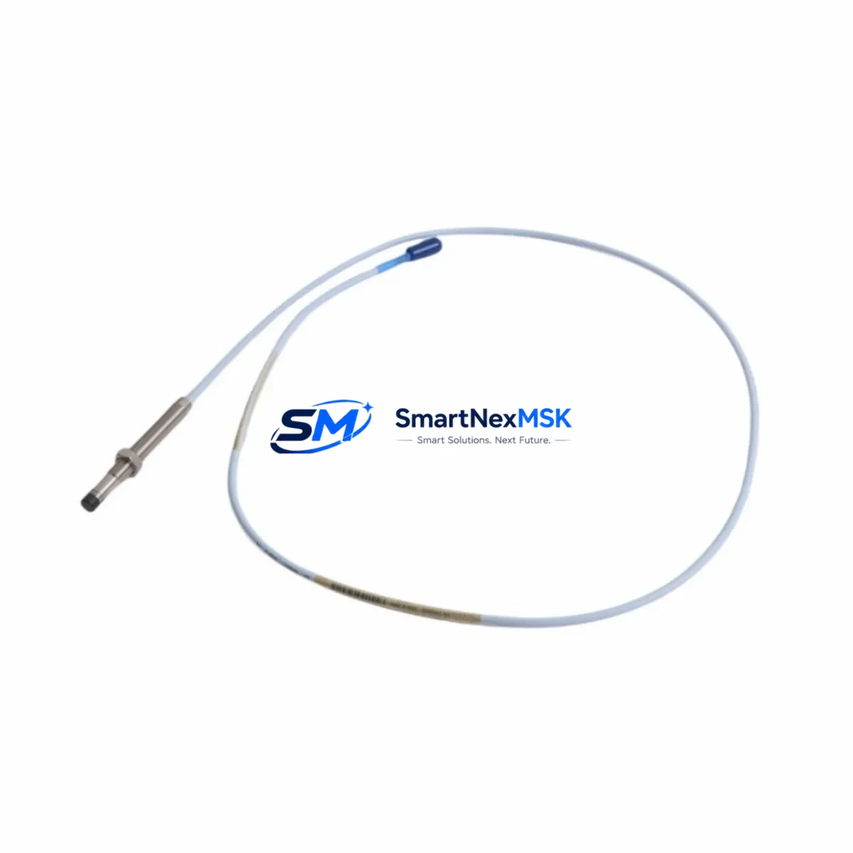
| Sensor Type | Eddy-Current Proximity Transducer, 8mm |
| Measurement Range | 0–90 mil pp (0–2.286 mm pp) radial vibration; 0–80 mil axial position |
| Output Sensitivity | 200 mV/mil (7.87 V/mm) nominal |
| Supply Voltage | −24 VDC (via 3300 XL Proximitor® driver) |
| Cable Length | 75 cm (integral armoured cable) |
| Thread / Tip Diameter | M10 × 1.0 / 8 mm |
| Temperature Range | −35 °C to +121 °C (probe tip) |
| Ingress Protection | IP67 (connector end sealed) |
| Compatible Driver | 3300 XL Proximitor® (e.g. 330180-X1-05, 330130-040-01-00) |
| Compatible Monitor | 3300/16 Dual Voting, 3500/42 Proximitor®/Seismic Monitor |
| Application | Radial vibration, axial position, differential expansion, speed |
| Origin | USA (Original Bently Nevada manufacture) |
| Warranty | 12 Months from date of delivery |
| Pre-shipment Test | Gap voltage, sensitivity, cable continuity, insulation resistance |
Maintenance Planning for Continuous Operation
A proximity transducer replacement is rarely an isolated task. When a maintenance or reliability engineer replaces the 330101-00-75-20-02-05 on a critical machine train, the surrounding measurement chain must be evaluated simultaneously to avoid repeat failures and to confirm the integrity of the protection system before the machine is returned to service.
Begin with the 3300 XL Proximitor® driver module (typically a 330180 or 330130 series unit). The driver converts the transducer’s impedance change into a calibrated voltage signal; a driver with degraded internal circuitry will produce incorrect gap voltage even with a new transducer installed. Verify the driver’s output at the nominal 1.27 mm (50 mil) gap: the reading should be −10.4 VDC ±0.5 V. If it falls outside this band, replace the driver concurrently.
Next, inspect the extension cable assembly (330130-040-01-00 or equivalent armoured extension). Eddy-current systems are highly sensitive to cable impedance; a damaged shield, corroded connector, or incorrect cable length will shift the system scale factor and introduce measurement error that no software compensation can fully correct. Confirm the cable is the correct matched length for the transducer and driver combination.
At the 3500 rack level, check the 3500/42 Proximitor®/Seismic Monitor input card for alarm setpoint integrity and I/O module health. Confirm that the OK relay output is functioning and that the 4–20 mA output to the DCS or historian is within calibration. If the plant uses a 3500/20 Power Supply module, verify that the −24 VDC rail is within ±1% under full rack load — a sagging supply rail is a common root cause of intermittent transducer faults that are misdiagnosed as sensor failures.
For plants running System 1® Evolution or System 1® Optimizer condition monitoring software, confirm that the channel configuration matches the new transducer’s sensitivity and gap range. An incorrect software scale factor will produce false alarms or, more dangerously, suppress real vibration events.
During the same maintenance window, inspect the terminal strip and field junction box for moisture ingress, loose terminations, and corrosion on the signal and shield conductors. In high-vibration environments, terminal screws can back off over time, introducing intermittent noise that mimics real shaft motion. Torque all terminations to specification and apply anti-corrosion compound where appropriate.
If the machine train includes a 3300 XL Keyphasor® transducer (such as the 330980 series), verify its gap voltage and signal quality at the same time. The Keyphasor® reference signal is used for phase measurement across all vibration channels; a degraded Keyphasor® will corrupt phase data for every channel on the machine, making it impossible to perform accurate balancing or orbit analysis.
For facilities maintaining older 3300/16 Dual Voting monitors alongside newer 3500 racks, confirm that the replacement transducer’s sensitivity is compatible with the monitor’s input range. Mixed-generation systems occasionally require sensitivity jumper changes on the monitor card when transducers are replaced.
Finally, update the maintenance management system (CMMS) record to reflect the transducer serial number, installation date, gap voltage at commissioning, and the next scheduled inspection interval. A well-documented baseline gap voltage is the single most valuable data point for detecting future transducer or shaft wear before it reaches alarm level.
Site Replacement Workflow
Step 1 — Isolation and permit: Obtain a work permit and confirm the machine is in a safe, de-energised state. For online replacement on non-critical machines, confirm with the control room that the channel can be bypassed without triggering a spurious shutdown.
Step 2 — Record baseline data: Before removing the old transducer, record the existing gap voltage, vibration amplitude, and phase from the monitor or System 1® display. This baseline is essential for commissioning the replacement and detecting any installation error.
Step 3 — Remove and inspect: Unscrew the transducer from the bracket. Inspect the bracket bore for wear, corrosion, or thread damage. A worn bracket will prevent accurate gap setting and should be replaced or re-machined before installing the new transducer.
Step 4 — Install and gap: Thread the 330101-00-75-20-02-05 into the bracket. Set the gap to the system-specified nominal value (typically 1.27 mm / 50 mil for 8mm transducers). Verify gap voltage at the Proximitor® output: target −10.4 VDC ±0.5 V. Lock the transducer with the jam nut to the specified torque.
Step 5 — Reconnect and verify: Reconnect the extension cable. Confirm OK relay status at the monitor. Verify that vibration readings are within expected baseline range before releasing the bypass and returning the channel to protection service.
Step 6 — Document: Record the new transducer serial number, installation gap voltage, and commissioning date in the CMMS. Retain the removed transducer for failure analysis if applicable.
Spare Parts Support FAQ
Q1: Is this an original Bently Nevada 330101-00-75-20-02-05 or an aftermarket equivalent?
This is an original Bently Nevada part manufactured to full OEM specification. It is not a third-party copy or reverse-engineered substitute. Original parts ensure correct sensitivity, gap range, and compatibility with 3300 XL Proximitor® drivers and 3500 series monitors without requiring recalibration of the measurement chain.
Q2: How do I confirm compatibility with my existing 3300 XL system before ordering?
Confirm the Proximitor® driver model number (330180 or 330130 series), the cable length currently installed, and the monitor input card type (3500/42 or 3300/16). The 330101-00-75-20-02-05 with 75 cm integral cable is compatible with standard 3300 XL driver configurations. If your system uses a different cable length or a non-standard bracket bore, contact us with your system drawing number before ordering.
Q3: What pre-shipment testing is performed, and what documentation is included?
Each unit undergoes gap voltage linearity verification, output sensitivity measurement at nominal gap, cable continuity and insulation resistance testing, and visual inspection of the connector and tip. A test record is available on request. Units are shipped in anti-static packaging with a certificate of conformance.
Q4: What does the 12-month warranty cover, and how is a warranty claim processed?
The 12-month warranty covers manufacturing defects, out-of-specification sensitivity, and premature failure under normal operating conditions. It does not cover physical damage from incorrect installation, chemical exposure beyond the rated environment, or operation outside the specified supply voltage range. To initiate a warranty claim, contact sales@smartnexmsk.com with the order number, installation date, and a description of the failure mode. Replacement units are dispatched within 3 business days of claim approval.
© 2026 SMARTNEXMSK. All rights reserved.
Original Source: https://smartnexmsk.com
Contact: sales@smartnexmsk.com | +86 18259474341


