Bently Nevada 330101-00-75-20-02-CN 3300 XL Retrofit-Ready Proximity Probe: Compatible Modernization for Legacy Vibration Monitoring Systems
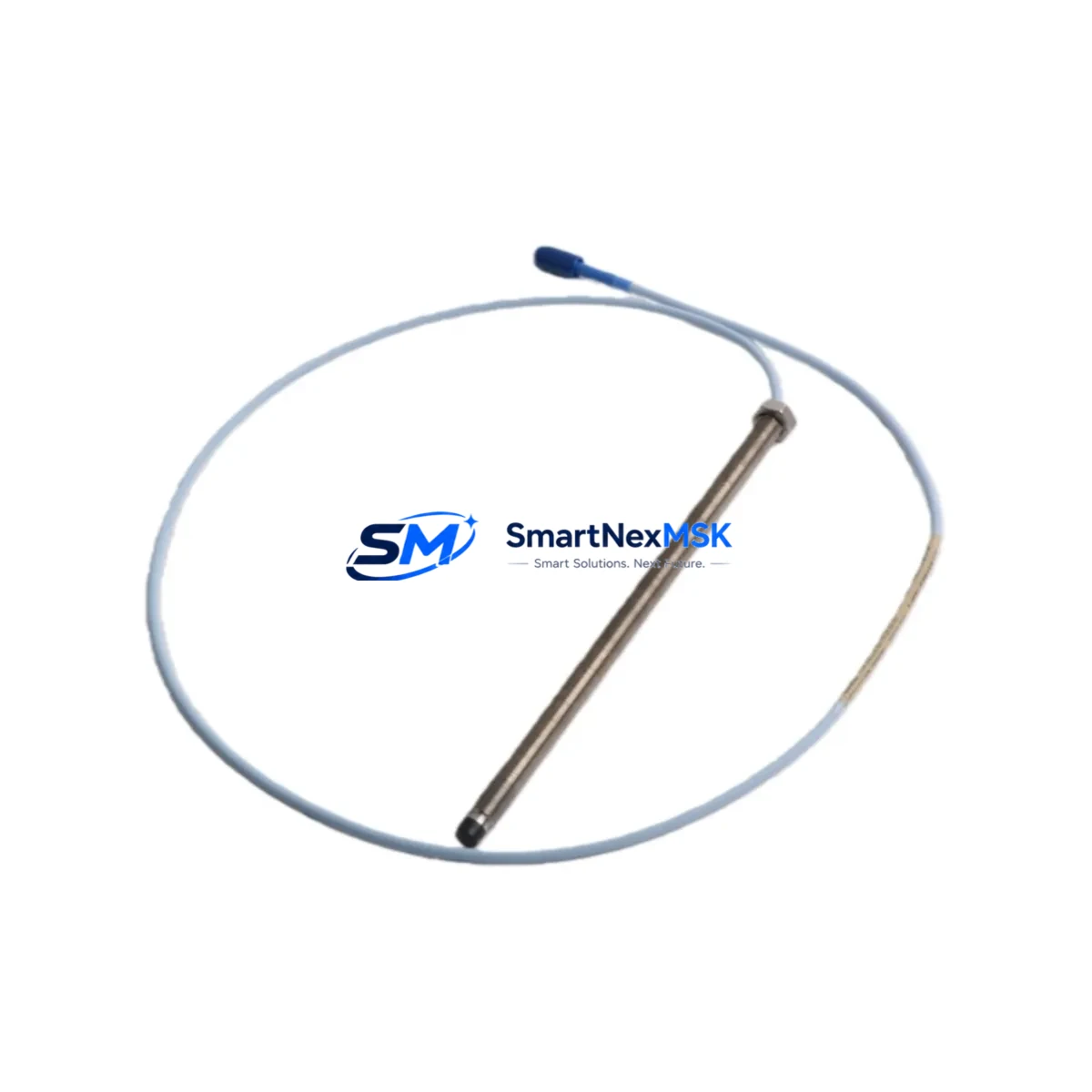
The Bently Nevada 330101-00-75-20-02-CN is an 8mm eddy-current proximity probe engineered for the 3300 XL Series vibration monitoring platform. Designed as a retrofit-ready replacement, this probe supports smooth migration from discontinued or aging field sensors without requiring changes to existing signal conditioning infrastructure, monitor rack wiring, or Bently Nevada System 1 software configurations. Whether you are restoring a failed measurement point, upgrading a worn probe assembly, or modernizing a legacy turbomachinery protection loop, the 330101-00-75-20-02-CN delivers verified compatibility and reliable performance in continuous operation environments.
Upgrade Compatibility Table
| Parameter | Details |
|---|---|
| SKU / Part Number | 330101-00-75-20-02-CN |
| Series Compatibility | Bently Nevada 3300 XL Series |
| Probe Diameter | 8mm Eddy-Current |
| Cable Length | 5m (integral cable) |
| Extension Cable | Compatible with 330130 Series extension cables |
| Driver / Proximitor | 3300 XL 8mm Proximitor (330180 Series) |
| Installation | M10 threaded tip, standard bracket mount |
| Communication Compatibility | Analog 4–20mA / voltage output via Proximitor |
| Replacement Recommendation | Direct drop-in for 330101-00-75-20-02-CN and equivalent discontinued variants |
| Commissioning Notes | Verify gap voltage (–10 VDC nominal), confirm scale factor, check OK relay status |
| Warranty | 12-Month Warranty — all units ship tested and documented |
Retrofit Planning for Existing Automation Systems
Replacing a proximity probe in an operating turbomachinery or rotating equipment installation requires careful coordination across multiple system layers. The 330101-00-75-20-02-CN integrates directly into existing 3300 XL monitor racks, but a complete retrofit assessment should address the full signal chain from the probe tip to the control room.
Begin by confirming the condition of the 330130 Series extension cable. In many legacy installations, the extension cable has been routed through conduit for years and may show insulation degradation or connector wear that will affect gap voltage stability. If the extension cable is being retained, measure its resistance and verify continuity before installing the new probe. A mismatched or degraded extension cable is one of the most common causes of erratic OK relay behavior after probe replacement.
Next, inspect the 330180 Series Proximitor module seated in the monitor rack. The Proximitor conditions the raw eddy-current signal and outputs the calibrated voltage used by the 3300 XL monitor card — typically a 3300/16 or 3300/20 dual-channel vibration monitor — to generate alarm and trip signals. Confirm that the Proximitor’s scale factor (typically 200 mV/mil or 7.87 V/mm) matches the probe specification. If the Proximitor is also being replaced as part of the upgrade, ensure the replacement unit is sourced from the same calibrated probe-cable-Proximitor system set to maintain measurement accuracy.
For installations where the 3300 XL rack also hosts a 3300/55 Keyphasor module, verify that the Keyphasor signal is unaffected by the probe swap. Phase reference data is critical for machinery diagnostics and must remain stable throughout the retrofit window. Similarly, if the rack includes a 3300/46M or 3300/50 temperature monitor card for bearing RTD or thermocouple inputs, confirm that those channels remain online during the probe replacement to maintain continuous thermal protection.
In control systems where the 3300 XL rack communicates upstream to a DCS or safety system via a 3500/92 or TDI communication gateway, coordinate with the control room team before breaking the measurement loop. Many facilities require a formal bypass authorization and a Management of Change (MOC) record before any protection-critical sensor is taken offline. Prepare the bypass documentation, notify the DCS operator, and confirm that the relevant vibration trip channel is placed in bypass mode in the System 1 software before disconnecting the probe.
After installing the 330101-00-75-20-02-CN, set the probe gap to achieve the nominal –10 VDC output at the Proximitor. Use a calibrated digital voltmeter at the Proximitor output terminals and adjust the probe standoff distance in small increments. Record the final gap voltage and confirm that the OK relay is energized. Restore the bypass, verify that the System 1 trend display shows a clean, stable vibration reading, and document the as-left gap voltage in the maintenance record. Ship-test documentation and a 12-month warranty certificate are included with every unit.
Downtime Control During System Migration
Minimizing unplanned downtime during a proximity probe replacement depends on preparation, not speed. Before the maintenance window opens, stage all replacement components — the 330101-00-75-20-02-CN probe, any required 330130 extension cable, and a spare 330180 Proximitor if the existing unit is suspect — at the work site. Pre-verify that the replacement probe has been bench-tested and that the gap voltage at a known standoff distance matches the expected value.
Where the process allows, schedule the probe replacement during a planned outage or a low-load period when a brief vibration protection bypass can be authorized. If the machine must remain running, work with the operations team to confirm that redundant protection channels — such as a second radial vibration probe on the same bearing journal — remain active and in service throughout the swap. Never bypass all protection channels simultaneously on a critical machine.
Preserve the original program logic in the System 1 software by exporting the current configuration before making any changes. If the replacement probe requires a scale factor adjustment in the monitor card, document the original setting and apply the new value only after the probe is installed and gapped. This approach protects the existing alarm and trip setpoints and avoids inadvertent changes to the machinery protection logic that could affect other measurement points in the same rack, including any active 3300/25 or 3300/20 monitor cards sharing the same rack power supply.
After restoration, run a short observation period — typically 15 to 30 minutes at operating speed — to confirm that vibration readings are stable, that no spurious alarms are generated, and that the OK relay remains energized. Log the final gap voltage, the date of replacement, and the unit serial number. A 12-month warranty covers all units supplied, and pre-shipment functional test records are available on request.
Retrofit Support FAQ
Q: Is the 330101-00-75-20-02-CN a direct replacement for the original Bently Nevada part?
A: Yes. The 330101-00-75-20-02-CN is a direct form-fit-function replacement for the original Bently Nevada part of the same SKU. It uses the same M10 thread, 8mm tip diameter, integral cable length, and connector type, and is compatible with the 330180 Series Proximitor and 3300 XL monitor cards without modification.
Q: What commissioning checks are required after installation?
A: After installation, set the probe gap to achieve –10 VDC ±0.25 VDC at the Proximitor output. Confirm the OK relay is energized, verify the vibration reading in System 1 is stable and within expected baseline range, and check that no alarm or trip conditions are active. Record the as-left gap voltage in the maintenance log.
Q: Can this probe be used with extension cables from other manufacturers?
A: Bently Nevada proximity probe systems are calibrated as matched sets — probe, extension cable, and Proximitor. Using non-OEM extension cables may affect scale factor accuracy and OK relay behavior. We recommend pairing the 330101-00-75-20-02-CN with genuine 330130 Series extension cables to maintain measurement integrity and warranty coverage.
Q: What does the 12-month warranty cover?
A: The 12-month warranty covers manufacturing defects, electrical performance within specification, and connector integrity. Each unit is functionally tested prior to shipment, and test documentation is available on request. Warranty claims are processed directly — contact sales@smartnexmsk.com with the unit serial number and a description of the issue.
© 2026 SMARTNEXMSK. All rights reserved.
Original Source: https://smartnexmsk.com
Contact: sales@smartnexmsk.com | +86 18259474341


