Bently Nevada 330101-00-77-20-02-05 Retrofit-Ready 3300 XL Proximity Transducer for Legacy Control Systems
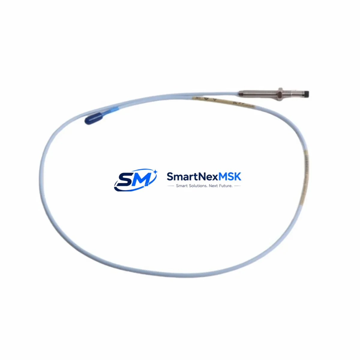
The Bently Nevada 330101-00-77-20-02-05 is an 8mm proximity transducer engineered for the 3300 XL Series vibration monitoring platform. Designed as a retrofit-ready, drop-in replacement for discontinued or aging transducer assemblies, this unit enables plant engineers and maintenance teams to restore full vibration monitoring capability without replacing the entire monitoring rack or reconfiguring the signal conditioning chain. Whether you are upgrading a legacy turbomachinery protection system, replacing a failed sensor on a critical compressor train, or modernizing a control cabinet that has been in service for over a decade, the 330101-00-77-20-02-05 delivers the dimensional accuracy, electrical compatibility, and signal integrity required for seamless integration into existing 3300 XL monitor channels.
This transducer is part of the Bently Nevada 3300 XL proximity system, which operates on the eddy-current sensing principle. The 330101-00-77-20-02-05 is rated for a nominal gap voltage of -10 VDC at 1.0 mm (40 mil) and provides a linear output range suitable for radial shaft vibration, axial position, and differential expansion measurements. The 8mm tip diameter and standard armored cable construction make it mechanically interchangeable with earlier 3300 series transducers in most bracket and probe holder configurations, significantly reducing installation time and downtime risk during planned or emergency replacements.
Upgrade Compatibility Table
| Parameter | 330101-00-77-20-02-05 (This Unit) | Notes / Retrofit Guidance |
|---|---|---|
| Tip Diameter | 8 mm | Compatible with standard 3300 XL probe holders; verify bracket thread pitch before installation |
| Cable Length | 5m (extension cable required for longer runs) | Pair with Bently Nevada 330130 extension cable for runs up to 9m total |
| Output Sensitivity | 7.87 V/mm (200 mV/mil) | Matches 3300 XL monitor input specification; no re-ranging required |
| Supply Voltage | -24 VDC nominal | Verify driver/monitor power supply capacity before hot-swap; 3500/40M and 3300/16 monitors confirmed compatible |
| Connector Type | Standard coaxial (BNC-compatible via adapter) | Direct replacement for earlier 330100 series; check junction box terminal labeling |
| Communication / Signal | Analog voltage output (passive eddy-current) | No protocol migration required; signal feeds directly into 3300 XL monitor or 3500 series rack |
| Mounting Thread | M10 x 1.0 | Confirm existing probe holder thread; re-use existing locknut where possible |
| Replacement Compatibility | 330101-00-77-20-02-05, 330101-00-77-20-02-00, earlier 3300 8mm variants | Cross-reference OEM part number before ordering; confirm gap voltage at commissioning |
| Warranty | 12 Months | Covers manufacturing defects; includes pre-shipment functional test report on request |
Retrofit Planning for Existing Automation Systems
Replacing a proximity transducer in a live turbomachinery or rotating equipment protection system requires careful pre-work to avoid unplanned shutdowns and to protect the integrity of the existing monitoring logic. Before removing the failed or end-of-life 330101-00-77-20-02-05 from the field, maintenance engineers should document the current gap voltage reading at the monitor channel input — typically displayed on the front panel of the Bently Nevada 3300/16 or 3500/40M monitor module — and record the baseline vibration amplitude and phase reference values from the operator HMI or DCS historian.
In systems where the 3300 XL transducer feeds into a Bently Nevada 3500 Series rack, the replacement procedure involves verifying that the 3500/42M or 3500/40M monitor card is configured for the correct transducer type and sensitivity. If the existing rack also houses a 3500/20 rack interface module or a 3500/22M transient data interface, confirm that the channel mapping in System 1 or the legacy Operator Display Unit (ODU) reflects the correct probe location tag before re-energizing the channel.
For plants running older DCS platforms — such as those using Honeywell TDC 3000 or Foxboro I/A Series controllers — the vibration signal from the 3300 XL monitor is typically transmitted as a 4–20 mA analog output to the DCS I/O card. In this configuration, no protocol migration is required; however, the DCS analog input card scaling and alarm setpoints should be verified against the new transducer’s calibration certificate. If the control system uses a Modbus RTU or FOUNDATION Fieldbus gateway to aggregate vibration data, confirm that the gateway’s channel configuration still maps correctly after the transducer swap.
When the retrofit involves upgrading from an older 3300 series (non-XL) transducer to the current 330101-00-77-20-02-05, engineers should also inspect the junction box wiring and terminal block labeling. The coaxial cable shield grounding practice differs between early 3300 and 3300 XL installations, and improper grounding can introduce noise into the vibration signal that triggers nuisance alarms. In cabinets where the transducer cable runs alongside power cables for variable frequency drives (VFDs) or motor control centers (MCCs), additional shielding or cable separation may be required to maintain signal integrity.
Common companion components sourced during the same retrofit window include the Bently Nevada 330130-080-00-00 extension cable, the 330180-X1-05 proximitor/driver, the 3500/40M proximitor monitor card, and the 3500/05 power supply module. In multi-channel installations, the 3500/20 rack interface module and 3500/22M transient data interface are frequently replaced at the same time to ensure the entire signal chain is on a consistent firmware and hardware revision. For systems that also monitor axial position or differential expansion, the 330103 series axial transducer and the 330106 series high-temperature transducer are often part of the same procurement package.
Downtime Control During System Migration
Minimizing unplanned downtime during a proximity transducer replacement is a primary concern for any plant operating rotating equipment under continuous production demands. The 330101-00-77-20-02-05 is stocked for same-week dispatch, which supports just-in-time replacement strategies and reduces the window between failure detection and restoration of full protection coverage.
For planned maintenance windows, the recommended approach is to pre-configure and bench-test the replacement transducer assembly — including the extension cable and proximitor driver — before the equipment is taken offline. This involves setting the gap to the nominal -10 VDC output using a calibrated gap-setting tool and verifying the output linearity across the full measurement range. A pre-shipment functional test report is available on request and can be used to satisfy site acceptance testing requirements without additional bench equipment.
During the actual swap, the existing probe holder and locknut should be inspected for thread wear and corrosion. If the holder is serviceable, the new 330101-00-77-20-02-05 can be installed directly, with the gap re-set to the OEM specification before the locknut is torqued. After installation, the monitor channel should be brought online in bypass mode — using the 3500/40M channel inhibit function or the equivalent bypass relay in the 3300/16 monitor — to allow the gap voltage and vibration baseline to stabilize before the protection logic is re-armed. This approach preserves the original program logic and alarm setpoints in the monitor and DCS, eliminating the need for any software changes and protecting the continuity of the field control system.
For emergency replacements where the equipment cannot be taken offline, consult the site safety plan and the monitor’s bypass procedure before proceeding. The 3500 Series rack supports channel-level bypass without affecting adjacent channels, which allows a single transducer to be replaced while the remaining channels continue to provide protection coverage.
Retrofit Support FAQ
Q: Is the 330101-00-77-20-02-05 a direct drop-in replacement for earlier 3300 series 8mm transducers?
A: In most installations, yes. The 330101-00-77-20-02-05 shares the same M10 x 1.0 mounting thread, 8mm tip diameter, and 200 mV/mil sensitivity as earlier 3300 series variants. However, engineers should verify the cable length, connector type, and gap voltage specification against the existing monitor channel configuration before installation, as minor revisions exist across suffix variants.
Q: What wiring checks are required before installing the replacement transducer?
A: Inspect the junction box terminal block for correct coaxial cable polarity (center conductor to signal, shield to ground), verify that the cable shield is grounded at one end only (typically at the monitor end), and confirm that the terminal labeling matches the channel tag in the DCS or System 1 configuration. If the existing wiring uses an older color-coding convention, cross-reference against the Bently Nevada installation drawing for the specific monitor model.
Q: How is compatibility with the 3500 Series rack verified before commissioning?
A: Power the monitor channel in bypass mode, connect the replacement transducer, and observe the gap voltage on the 3500/40M front panel display or via the System 1 software channel view. The gap voltage should read between -9.5 VDC and -10.5 VDC at the nominal installation gap. If the reading is outside this range, adjust the probe gap using a non-metallic gap-setting tool until the target voltage is achieved, then torque the locknut and re-verify.
Q: What does the 12-month warranty cover, and is a test report available?
A: The 12-month warranty covers manufacturing defects in materials and workmanship from the date of shipment. A pre-shipment functional test report documenting gap voltage linearity, output sensitivity, and insulation resistance is available on request at no additional charge. Warranty claims are processed via our sales team with a standard RMA procedure; replacement units are dispatched within 5 business days of claim approval.
© 2026 SMARTNEXMSK. All rights reserved.
Original Source: https://smartnexmsk.com
Contact: sales@smartnexmsk.com | +86 18259474341


