Bently Nevada 330101-00-96-10-02-05 Maintenance-Ready Spare for 3300 XL Automation
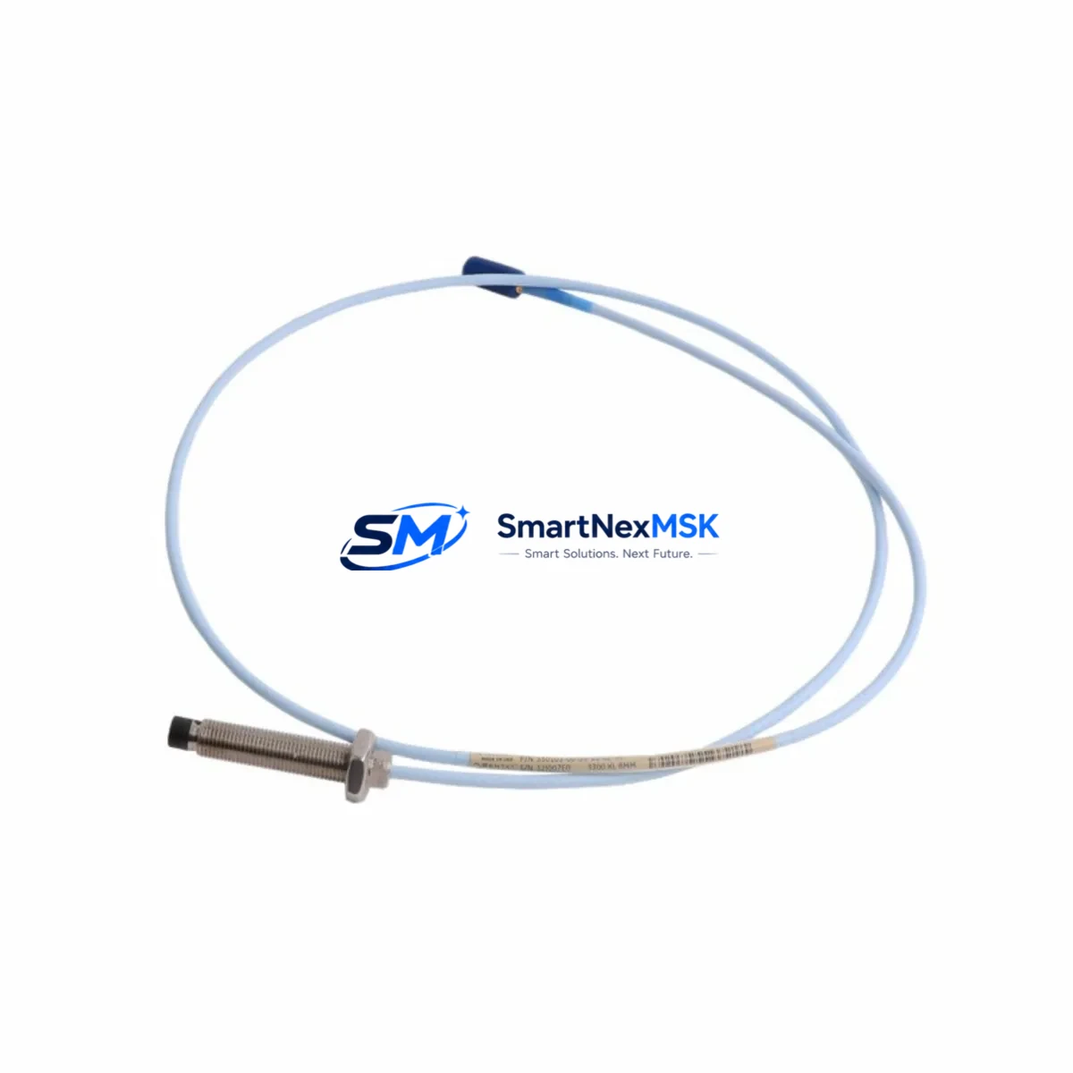
The Bently Nevada 330101-00-96-10-02-05 is an original 8mm eddy-current proximity probe engineered for the 3300 XL continuous vibration monitoring system. For maintenance engineers managing rotating machinery — turbines, compressors, pumps, and gearboxes — this probe is a critical front-line sensor in any condition-monitoring architecture. Unplanned downtime caused by a failed or degraded proximity probe can cascade into extended outages across an entire train. Stocking a verified original replacement is the most effective single action a maintenance team can take to protect uptime.
This spare is sourced, inspected, and shipped with full traceability. Each unit undergoes pre-shipment functional verification covering output voltage linearity, gap sensitivity, and cable continuity before dispatch. A 12-month warranty covers manufacturing defects and performance deviation from published specifications.
Spare Maintenance Table
| Parameter | Specification |
|---|---|
| Part Number | 330101-00-96-10-02-05 |
| Brand | Bently Nevada |
| Series | 3300 XL |
| Probe Type | 8mm Eddy-Current Proximity Probe |
| Cable Length | 5m (extension cable) |
| Sensitivity | 7.87 V/mm (200 mV/mil) |
| Linear Range | 0.25 mm – 2.26 mm (10–89 mil) |
| Supply Voltage | –24 VDC (nominal) |
| Operating Temperature | –35°C to +177°C |
| Thread Size | M10 × 1 |
| Connector | 3-pin MIL-C-5015 compatible |
| Compatibility | 3300 XL Monitor, 3500/40M, 3500/42M, 3500/45 |
| Application | Shaft radial vibration, axial position, differential expansion |
| Condition | Original, New / Tested Surplus |
| Warranty | 12 Months |
| Origin | USA |
Maintenance Planning for Continuous Operation
When a 330101-00-96-10-02-05 probe is flagged during routine point inspection or condition monitoring review, experienced maintenance engineers know that the probe itself is rarely the only component requiring attention. A complete corrective maintenance cycle for a 3300 XL channel should include inspection of the paired 330130-080-00-00 extension cable for jacket abrasion, connector corrosion, and continuity. The 330180-X1-05 proximitor/oscillator driver — the signal conditioning module that powers the probe and converts gap distance to a DC voltage — should be bench-tested or swapped with a known-good unit, since a degraded driver can mimic probe failure symptoms and lead to misdiagnosis.
At the rack level, verify the 3500/40M proximitor I/O module or 3500/42M velocity monitor channel card for alarm setpoint integrity and OK relay status. The 3500/15 power supply module supplying –24 VDC to the proximitor rail should be load-tested; a sagging supply voltage directly degrades probe sensitivity and can trigger nuisance trips. If the machine train includes thrust position monitoring, the 330103-00-08-10-02-05 thrust probe in the same bearing housing should be inspected simultaneously to avoid a second outage within the same planned window.
For facilities running older 3300 Series (non-XL) racks, confirm that the replacement probe’s sensitivity constant and linear range are compatible with the installed monitor’s configuration before installation. The 3300/16 monitor and 3300/20 dual-channel monitor accept 3300 XL probes with appropriate gap and sensitivity reconfiguration. Document the as-found and as-left gap voltage readings in the maintenance management system to establish a baseline for the next inspection cycle.
Procurement engineers building a spare parts bill of materials for a turbomachinery train should consider holding at minimum one probe per monitored bearing position, one extension cable per probe, and one proximitor driver per two channels as a rotating spare. For critical assets with no installed redundancy, a complete channel spare kit — probe, cable, and driver — eliminates the longest lead-time risk in an emergency.
Site Replacement Workflow
Step 1 — Isolation and lockout: Coordinate with operations to place the affected channel in bypass mode at the 3500 rack or 3300 monitor before physical work begins. Confirm the OK relay is de-energized and the channel alarm is suppressed in the DCS or safety system.
Step 2 — As-found documentation: Record the existing probe gap voltage (typically –10 VDC at nominal gap), cable routing, and connector torque condition. Photograph the probe tip and target area for wear pattern analysis.
Step 3 — Probe removal: Loosen the locknut and back the probe out of the bracket. Inspect the target area on the shaft for scoring, pitting, or runout that could affect the replacement probe’s output. Clean the target surface if required.
Step 4 — Installation and gapping: Thread the 330101-00-96-10-02-05 into the bracket. Set the gap to the manufacturer-specified nominal (typically 1.0–1.5 mm / 40–60 mil) using a non-ferrous feeler gauge or by monitoring the DC output voltage from the proximitor. Torque the locknut to specification and secure the cable with appropriate clamps to prevent vibration-induced connector wear.
Step 5 — Functional verification: With the channel returned to service, confirm the OK light is illuminated, the gap voltage is within the linear range, and the vibration reading is consistent with adjacent channels and historical baseline. Remove the bypass and restore normal monitoring.
This workflow applies equally to radial vibration, axial position, and differential expansion channels, making the 330101-00-96-10-02-05 a versatile spare across multiple measurement functions within the same 3300 XL or 3500 system installation.
Spare Parts Support FAQ
Q1: Is the 330101-00-96-10-02-05 compatible with both 3300 and 3500 series monitors?
The 330101-00-96-10-02-05 is a 3300 XL series probe and is fully compatible with 3300 XL monitors. It is also compatible with 3500 series monitors (3500/40M, 3500/42M, 3500/45) when used with the correct 330180 series proximitor driver. Always verify the monitor’s configured sensitivity constant matches the probe’s 7.87 V/mm output before installation.
Q2: How do you verify the probe is functional before installation?
Each unit shipped from our inventory has been pre-tested for output linearity, gap sensitivity, and cable continuity. Upon receipt, we recommend a bench verification using a calibrated proximitor driver and a steel target plate: confirm the output voltage sweeps linearly from approximately –2 VDC (near gap) to –18 VDC (far gap) across the specified linear range. Any deviation exceeding ±5% of the sensitivity constant indicates a defective unit.
Q3: What is the recommended spare inventory strategy for a facility with 20+ monitored bearing positions?
Industry best practice for critical rotating machinery is to hold 10–15% of installed probe count as on-site spares, with a minimum of two probes per machine train. For facilities with long procurement lead times or remote locations, a complete channel kit (probe + extension cable + proximitor driver) per critical train is recommended. This eliminates the risk of a single component extending an unplanned outage beyond the first shift.
Q4: What warranty and post-shipment support is provided?
All units carry a 12-month warranty from the date of shipment, covering manufacturing defects and performance deviation from Bently Nevada published specifications. If a unit fails within the warranty period, we provide a replacement or full refund after review of the failure documentation. Our technical team is available to support installation verification, gap-setting guidance, and compatibility confirmation for your specific monitor configuration.
© 2026 SMARTNEXMSK. All rights reserved.
Original Source: https://smartnexmsk.com
Contact: sales@smartnexmsk.com | +86 18259474341


