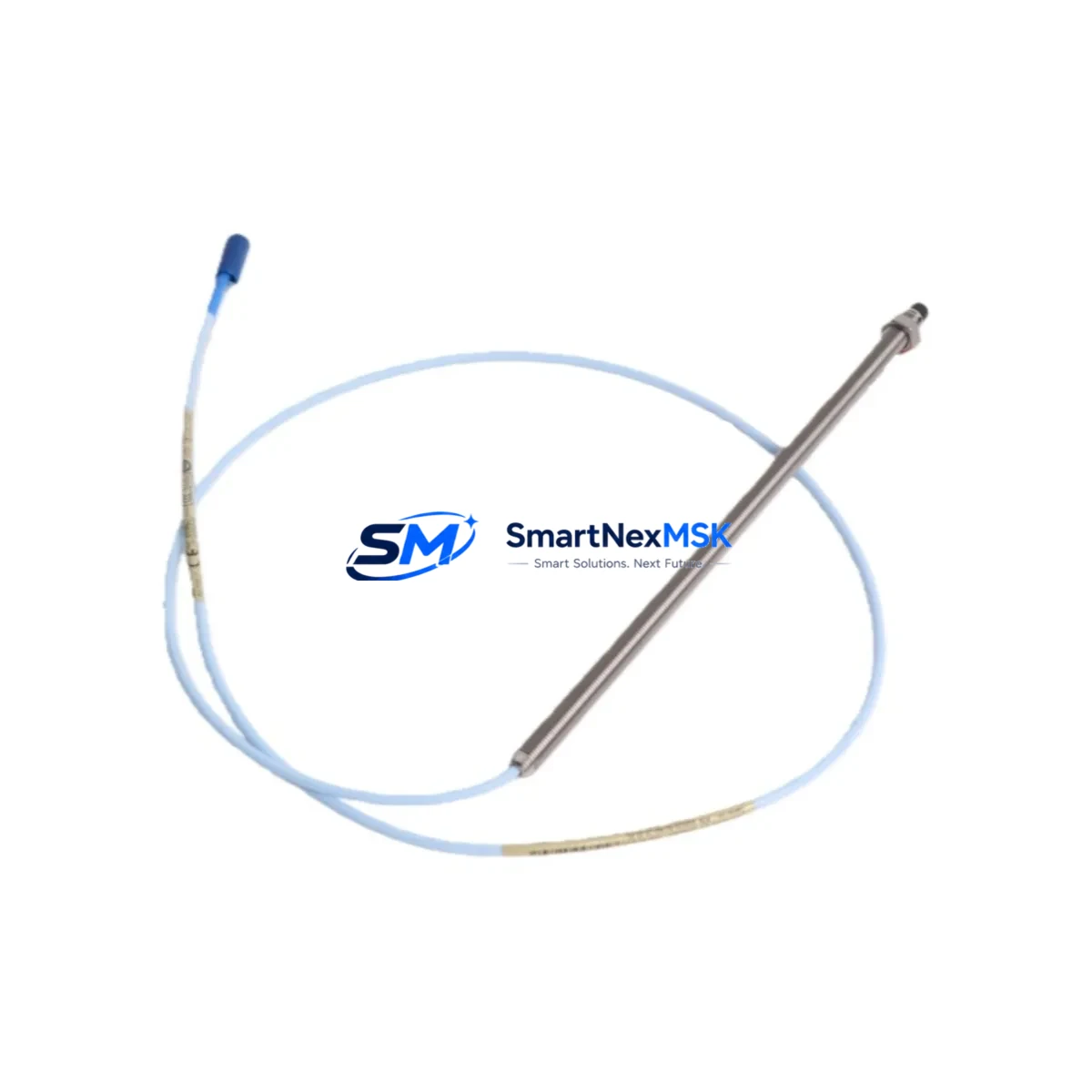
Bently Nevada 330101-00-96-10-02-CN Retrofit-Ready Proximity Probe for 3300 XL Control Systems
The Bently Nevada 330101-00-96-10-02-CN is a 96-inch (2.4 m), 10 mm proximity probe designed for seamless integration into Bently Nevada 3300 XL continuous vibration monitoring systems. Whether you are replacing a failed sensor on an aging turbine protection panel, upgrading a legacy 3300 Series installation to current 3300 XL architecture, or restoring a mothballed machine train to service, this probe delivers the electrical and mechanical compatibility required for a smooth, low-risk retrofit.
Industrial facilities operating steam turbines, gas compressors, centrifugal pumps, and large rotating machinery depend on the 3300 XL platform for real-time shaft displacement, radial vibration, and axial position monitoring. When a probe in this chain fails or reaches end-of-life, the replacement must match the original transducer system’s sensitivity (7.87 V/mm), gap voltage range, and cable impedance characteristics precisely. The 330101-00-96-10-02-CN meets these requirements and is verified compatible with the 3300 XL 8-mm and 10-mm transducer system signal conditioning chain.
Upgrade Compatibility Table
| Parameter | Detail |
|---|---|
| SKU / Part Number | 330101-00-96-10-02-CN |
| Compatible Platform | Bently Nevada 3300 XL Monitoring System |
| Probe Tip Diameter | 10 mm |
| Extension Cable Length | 96 inches (2.4 m) |
| Sensitivity | 7.87 V/mm (200 mV/mil) |
| Operating Gap Range | 0.25 mm – 2.25 mm (10 – 90 mil) |
| Connector Type | Standard BNC / coaxial, compatible with 3300 XL driver modules |
| Driver / Proximitor Compatibility | 3300 XL 8 mm / 10 mm Proximitor® Sensor (e.g., 330180 series) |
| Installation Interface | M10 × 1 threaded body; fits standard probe holder brackets |
| Communication / Signal | Analog DC voltage output; integrates directly with 3500/40M, 3500/42M monitor cards |
| Replacement Recommendation | Direct drop-in for 330101-00-96-10-02-CN; verify gap voltage after installation |
| Commissioning Focus | Gap voltage calibration, OK relay status, and channel bypass during hot swap |
| Warranty | 12-Month Warranty — covers manufacturing defects and electrical performance |
Retrofit Planning for Existing Automation Systems
A successful retrofit of the 330101-00-96-10-02-CN into an operating plant requires careful coordination across multiple system layers. Before removing the failed probe, engineers should confirm that the associated Bently Nevada 3500/40M Proximitor® / Velomitor® Input Module or 3500/42M Proximitor® / Velomitor® Input Module is functioning correctly and that the channel can be placed in bypass mode to prevent a spurious trip during the swap.
The extension cable routing must be inspected end-to-end. The 330130-045-00-00 or equivalent 3300 XL extension cable should be checked for continuity and shield integrity before the new probe is connected. A damaged extension cable is a common root cause of recurring probe failures and is frequently overlooked during emergency replacements. Similarly, the 330180-X1-05 Proximitor® Sensor driver module mounted in the field junction box should be verified for correct bias voltage output (typically −18 VDC to −24 VDC) before the new probe is energized.
On the rack side, the 3500 Monitoring System chassis — whether a 3500/05 or 3500/15 rack — should be inspected for backplane connector integrity. Corroded or bent pins on the rack’s I/O module slots can introduce noise that mimics a faulty probe. If the plant is running an older 3300 Series rack rather than the current 3500 architecture, this retrofit is also an appropriate moment to evaluate a full rack migration: the 3300 XL probe and Proximitor® system is electrically compatible with both generations, but the 3500 platform offers superior diagnostics, Modbus RTU and Ethernet/IP communication options, and integration with modern DCS and SCADA environments.
For facilities using a Bently Nevada System 1 condition monitoring software platform, the channel configuration — including full-scale range, alert and danger setpoints, and OK limits — must be re-verified after probe replacement. If the plant has migrated or is migrating from System 1 Evolution to System 1 version 21.x, this is also the time to confirm that the new probe’s transducer parameters are correctly entered in the software database to avoid false OK-relay dropout events.
Where the control system interfaces with a DeltaV DCS, Honeywell Experion PKS, or a third-party safety instrumented system via hardwired relay contacts or FOUNDATION Fieldbus, the I/O mapping and alarm logic should be reviewed before returning the channel to service. The 3500/92 Communication Gateway Module — if installed — should also be checked to confirm that the Modbus register map for the affected channel remains intact after any firmware updates performed during the maintenance window.
Downtime Control During System Migration
Minimizing unplanned downtime is the primary operational concern when replacing a proximity probe on a running machine train. The recommended approach is to use the 3500 rack’s channel bypass function to suppress the affected channel’s trip output before breaking the coaxial connection. This preserves the machine’s protection status on all remaining active channels while the swap is performed.
Before disconnecting the probe, document the existing gap voltage reading from the 3500/40M or 3500/42M monitor display or from System 1. This value serves as the baseline for post-installation gap calibration. The target gap for a 10 mm probe in a typical radial vibration application is 1.0 mm to 1.5 mm, corresponding to approximately −10 VDC to −12 VDC on the Proximitor® output. Achieving this gap before releasing the bypass ensures that the channel returns to service with a valid OK status immediately.
If the machine cannot be taken offline, a hot-swap procedure is possible provided the channel is bypassed, the replacement probe is pre-gapped using a non-conductive feeler gauge or a portable gap meter, and the coaxial connector is made up cleanly before the bypass is released. All original program logic in the associated safety PLC or ESD system — including any interlock permissives tied to the vibration channel — should remain unchanged throughout the procedure. No PLC program download or HMI screen reconfiguration is required for a like-for-like probe replacement.
Post-installation, a 30-minute observation period at normal operating speed is recommended to confirm that the gap voltage is stable, the OK relay is energized, and the vibration reading is consistent with historical baseline data. All findings should be recorded in the plant’s maintenance management system before the work order is closed.
Retrofit Support FAQ
Q1: Is the 330101-00-96-10-02-CN a direct replacement for the original Bently Nevada part?
Yes. This unit is a form-fit-function replacement for the original Bently Nevada 330101-00-96-10-02-CN proximity probe. It uses the same 10 mm tip diameter, 96-inch extension cable, M10 × 1 thread, and 7.87 V/mm sensitivity, and is compatible with the 3300 XL Proximitor® driver and 3500 Series monitor cards without any wiring or configuration changes.
Q2: What pre-shipment testing is performed on this probe?
Each unit undergoes electrical performance verification prior to shipment, including sensitivity check, OK voltage output confirmation, and coaxial connector continuity test. A test report is available upon request. The probe is covered by a 12-month warranty against manufacturing defects and electrical performance deviations from specification.
Q3: Can this probe be used with an older 3300 Series rack instead of the 3300 XL or 3500 platform?
The 330101-00-96-10-02-CN is designed for the 3300 XL transducer system. While the physical connector and thread are compatible with older 3300 Series installations, the Proximitor® driver module must also be a 3300 XL type (e.g., 330180 series) to ensure correct bias voltage and sensitivity matching. Using a legacy 3300 (non-XL) Proximitor® with this probe may result in out-of-specification gap voltage and should be verified by a qualified instrumentation engineer before commissioning.
Q4: What is the lead time and how is the probe packaged for international shipment?
In-stock units ship within 1–3 business days. The probe is packaged in anti-static foam with the coaxial connector protected by a dust cap, and the threaded tip covered to prevent damage in transit. Export documentation including commercial invoice, packing list, and country-of-origin certificate (CN) is provided for customs clearance. Expedited shipping options are available for urgent plant shutdowns.
© 2026 SMARTNEXMSK. All rights reserved.
Original Source: https://smartnexmsk.com
Contact: sales@smartnexmsk.com | +86 18259474341


