Bently Nevada 330101-02-12-05-01-CN Retrofit-Ready Proximity Transducer for 3300 XL Control Systems
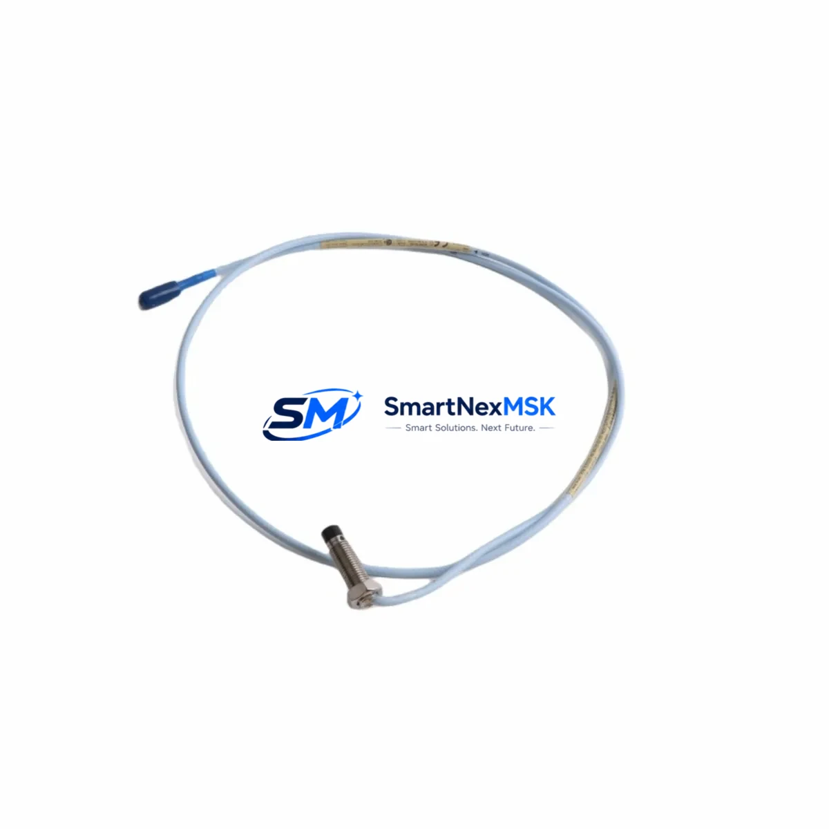
The Bently Nevada 330101-02-12-05-01-CN is a high-precision eddy-current proximity transducer engineered for the 3300 XL Series continuous machinery monitoring platform. Designed as a retrofit-ready, drop-in replacement for aging or discontinued transducer assemblies, this unit delivers reliable non-contact vibration, position, and eccentricity measurement in rotating machinery applications including turbines, compressors, pumps, and motors. Whether you are upgrading a legacy 3300 Series installation or restoring a critical monitoring loop after a field failure, the 330101-02-12-05-01-CN provides the dimensional compatibility, signal output, and cable length specification required for seamless integration into existing 3300 XL monitor racks without reprogramming the host system.
This transducer operates on the standard Bently Nevada proximitor/driver architecture, producing a linear DC voltage output proportional to the gap between the probe tip and the observed target surface. The -CN suffix designates the connector style and cable configuration optimized for panel-mount and conduit-entry installations common in petrochemical, power generation, and heavy industrial environments. Inventory is maintained in stock for immediate dispatch, and every unit ships with a 12-month warranty covering manufacturing defects and signal performance.
Upgrade Compatibility Table
| Parameter | 330101-02-12-05-01-CN | Notes / Retrofit Guidance |
|---|---|---|
| Series Compatibility | Bently Nevada 3300 XL | Direct replacement for 3300 XL proximity transducer assemblies |
| Output Signal | -18 VDC nominal (linear DC) | Verify driver/proximitor input range before installation |
| Cable Length | 5 m (extension cable required for longer runs) | Use Bently Nevada 330130 series extension cables to reach proximitor |
| Connector Type | -CN standard industrial connector | Confirm mating connector on junction box or proximitor housing |
| Thread / Mounting | M8 × 1 probe tip thread | Check existing bracket bore; re-tap if replacing from imperial-thread legacy probe |
| Target Gap Range | 0.25 mm – 2.25 mm (linear range) | Re-gap after installation; record baseline gap voltage in DCS historian |
| Monitor Compatibility | 3300/16 XL, 3300/20 XL, 3300/25 XL monitors | No firmware change required; alert/danger setpoints preserved |
| Communication Protocol | Analog 4–20 mA / DC voltage to 3500 or System 1 gateway | Verify System 1 tag mapping if migrating from older 3300 non-XL monitors |
| Installation Requirement | Grounded conduit, shielded cable, isolated mounting bracket | Avoid ground loops; use Bently Nevada recommended grounding practice |
| Warranty | 12 Months | Covers signal linearity, connector integrity, and manufacturing defects |
Retrofit Planning for Existing Automation Systems
Replacing a proximity transducer in a live machinery protection system requires careful coordination across multiple hardware layers. Before removing the 330101-02-12-05-01-CN’s predecessor from the field, engineers should document the current gap voltage reading from the 3300 XL monitor front panel or from the System 1 condition monitoring software historian. This baseline value is critical for re-gapping the new probe to the same operating clearance and confirming that the replacement unit falls within the monitor’s configured alert and danger thresholds.
In a typical 3300 XL rack, the proximity transducer connects through a 330130-series extension cable to a 3300 XL proximitor/driver module mounted in the monitor rack. The proximitor converts the probe’s raw impedance signal into the calibrated DC voltage that the 3300/16 XL or 3300/20 XL monitor card reads. When replacing the transducer, it is essential to verify that the replacement proximitor — if also being swapped — carries the same system sensitivity (V/mm) as the original, since mismatched sensitivity factors will shift the gap voltage reading and trigger false alarms or mask real vibration events.
For installations migrating from the older non-XL 3300 Series to the 3300 XL platform, the rack backplane and I/O terminal assignments may differ. The 3300 XL rack accepts standard 19-inch panel mounting and uses a dedicated power supply module — typically a 3300/05 power supply — that must be sized to support the full complement of monitor cards and proximitor loads. During the upgrade, engineers should audit the existing terminal block wiring, confirm that the field cable shield is terminated at one end only (typically at the proximitor), and verify that the machine train tag in the System 1 database is mapped to the new monitor card slot address.
Where the control system interfaces with a DCS or safety instrumented system via a 3500/92 communication gateway or a Modbus TCP interface card, the tag list and I/O address mapping should be validated in the DCS engineering workstation before the machine is returned to service. HMI screens displaying shaft vibration, axial position, or eccentricity trends should be checked to confirm that the engineering unit scaling and alarm limits reflect the new transducer’s calibration data. If the site uses a Rockwell Automation ControlLogix or Siemens S7-300/S7-400 PLC as the supervisory controller, the analog input card receiving the 4–20 mA retransmission signal from the 3300 XL monitor should be verified for correct scaling in the ladder logic or function block program.
For sites operating mixed fleets of rotating equipment, the same retrofit workflow applies to radial vibration, axial thrust, and speed/phase reference channels. The 330101-02-12-05-01-CN is commonly deployed alongside 330180-series speed sensors, 330105-series standard proximity probes, and 3300 XL keyphasor modules to form a complete shaft monitoring assembly. Ensuring that all transducers in a given machine train are replaced or verified simultaneously reduces the risk of mismatched calibration data corrupting the overall vibration signature baseline stored in the System 1 historian.
Downtime Control During System Migration
Minimizing unplanned downtime during a proximity transducer replacement begins with pre-staging all replacement components before the maintenance window opens. For the 330101-02-12-05-01-CN, this means having the replacement probe, the correct length of 330130 extension cable, a calibrated gap tool or feeler gauge set, and a laptop loaded with System 1 or the 3300 XL configuration software ready at the work site before the machine is taken offline.
The recommended sequence is to place the 3300 XL monitor channel into bypass mode — using the front-panel bypass switch or the System 1 software bypass command — before disconnecting the field cable. This prevents the monitor from issuing a spurious danger trip to the machine protection relay or the DCS interlock logic while the probe is being changed. The original program logic in the PLC or DCS is preserved throughout this process because the bypass command is applied at the monitor level, not at the controller level, and the controller continues to execute its scan cycle normally.
After the new 330101-02-12-05-01-CN is installed and gapped, the channel should be brought out of bypass incrementally: first confirm the gap voltage is within the linear range, then verify the vibration reading is stable and consistent with adjacent channels on the same machine train, and finally release the bypass and confirm that no alarms are active before restarting the machine. This structured commissioning sequence — gap check, signal verification, alarm confirmation, bypass release — typically takes 15 to 30 minutes per channel and can be completed without modifying any PLC program, DCS configuration, or HMI display, preserving full control continuity throughout the migration.
Retrofit Support FAQ
Q1: Is the 330101-02-12-05-01-CN a direct drop-in replacement for the standard 330101-02-12-05-01?
A: Yes. The -CN suffix designates the connector variant. The probe tip geometry, thread specification, cable length, and output sensitivity are identical to the base model. No changes to the proximitor, monitor card, or system configuration are required when substituting the -CN variant into an existing 3300 XL installation.
Q2: What commissioning checks are required after installation?
A: After mechanical installation, measure the gap voltage at the proximitor output and confirm it falls within the monitor’s configured linear range (typically -10 VDC ± 2 V at nominal gap). Record the as-found and as-left gap values in the maintenance management system. Verify that the vibration reading on the 3300 XL monitor front panel or System 1 display is stable and within the expected baseline range for the machine at its normal operating speed and load.
Q3: Can this transducer be used with a Bently Nevada 3500 Series monitor rack?
A: The 330101-02-12-05-01-CN is calibrated and specified for the 3300 XL platform. While the physical probe dimensions are compatible with 3500 Series proximitor inputs, the system sensitivity and calibration data are optimized for 3300 XL monitors. If deploying into a 3500 rack, verify the proximitor part number and system sensitivity specification with the site instrumentation engineer before installation.
Q4: What does the 12-month warranty cover?
A: The 12-month warranty covers manufacturing defects, signal linearity performance within the published specification, and connector integrity under normal operating conditions. Each unit undergoes pre-shipment functional testing to verify output voltage linearity across the full gap range. Warranty claims are processed through SMARTNEXMSK’s technical support team with a typical response time of one business day.
© 2026 SMARTNEXMSK. All rights reserved.
Original Source: https://smartnexmsk.com
Contact: sales@smartnexmsk.com | +86 18259474341


