Bently Nevada 330101-10-27-05-02-00 Spare 3300 XL: Maintenance-Ready Proximity Probe for Industrial Downtime Control
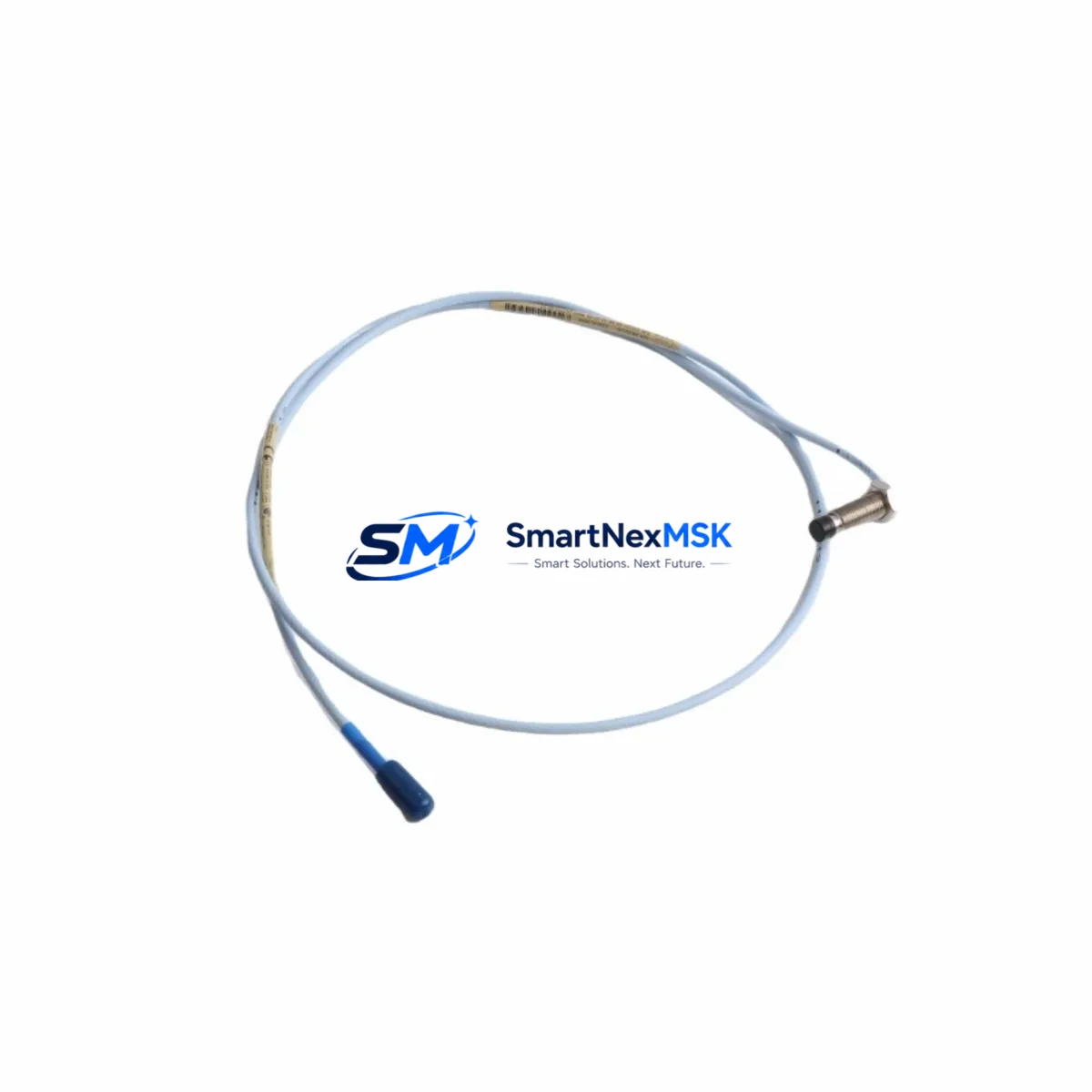
The Bently Nevada 330101-10-27-05-02-00 is an 8mm eddy current proximity probe engineered for the 3300 XL Series continuous machinery monitoring system. Designed to measure radial shaft vibration, axial position, and differential expansion on rotating equipment, this probe is a critical spare component for turbines, compressors, pumps, and gearboxes operating under API 670 protection standards. Maintaining a verified stock of this probe directly reduces unplanned downtime risk and supports rapid fault isolation during machinery trips.
For maintenance engineers managing aging turbomachinery or DCS-integrated protection systems, the 330101-10-27-05-02-00 represents a high-priority line item in any spare parts strategy. Its 8mm tip diameter, 5-metre integral cable, and -24 VDC bias voltage output make it a direct replacement for worn or damaged probes without requiring recalibration of the 3300 XL monitor rack — provided the replacement probe, extension cable, and proximitor driver are sourced as a matched system.
Every unit shipped from SMARTNEXMSK undergoes pre-shipment electrical verification including tip resistance, cable continuity, and output voltage linearity checks. Units are packaged in anti-static foam with original-specification labelling and are covered by a 12-month warranty from the date of shipment.
Spare Maintenance Table
| Parameter | Specification |
|---|---|
| SKU / Part Number | 330101-10-27-05-02-00 |
| Brand | Bently Nevada |
| Series | 3300 XL |
| Probe Type | 8mm Eddy Current Proximity Probe |
| Tip Diameter | 8 mm |
| Cable Length | 5 metres (integral) |
| Bias Voltage Output | -24 VDC (nominal) |
| Sensitivity | 7.87 V/mm (200 mV/mil) |
| Linear Range | 0.25 – 2.54 mm (10 – 100 mil) |
| Operating Temperature | -35°C to +177°C |
| Compliance Standard | API 670, CE |
| Compatible Monitor | 3300 XL Series (3300/16, 3300/20, 3300/25, 3300/46, 3300/55) |
| Compatible Proximitor | 330180 Series, 330130 Series |
| Compatible Extension Cable | 330130-045-00-CN, 330130-080-00-CN |
| Application | Radial vibration, axial position, differential expansion |
| Target Material | AISI 4140 steel or equivalent ferromagnetic alloy |
| Installation | Threaded probe holder, jam-nut secured, gap set to 1.27 mm (50 mil) |
| Warranty | 12 Months from shipment date |
| Pre-Shipment Test | Tip resistance, cable continuity, output voltage linearity |
| Origin | USA |
Maintenance Planning for Continuous Operation
When a 330101-10-27-05-02-00 probe is flagged for replacement — whether due to a high vibration alarm, a gap voltage drift outside the -10 to -18 VDC window, or physical damage to the probe tip or cable jacket — the replacement workflow should extend beyond the probe itself. A thorough site inspection at this point prevents repeat failures and maximises the value of the planned outage window.
Begin by verifying the 330180 Series Proximitor/Seismoprobe driver module mounted in the field junction box. Proximitor output drift is a common root cause of false probe alarms; if the probe tests within specification on the bench but the monitor still reads abnormal, the proximitor is the next suspect. Simultaneously, inspect the 330130 Series extension cable connecting the probe to the proximitor — cable jacket abrasion, connector corrosion, or shield continuity failures account for a significant share of field measurement errors.
At the 3300 XL monitor rack, confirm that the channel card (such as the 3300/16 Dual Voting or 3300/20 Radial Vibration module) is seated correctly and that the OK relay output is functioning. A failed OK relay can mask a genuine probe fault or generate nuisance trips. While the rack is accessible, inspect the 3300/46 Keyphasor module if the machine uses phase-referenced vibration analysis — a degraded Keyphasor signal will corrupt all vector measurements across the protection system.
For machines where the 3300 XL system feeds a System 1 Evolution condition monitoring platform or a third-party DCS via 4–20 mA retransmission, verify that the analogue output scaling has not drifted after the probe swap. Check the barrier or galvanic isolator in the intrinsically safe loop if the probe is installed in a hazardous area — a degraded Zener barrier will introduce measurement offset that is difficult to distinguish from a probe gap error.
Finally, review the terminal block and field wiring in the junction box. Loose terminations on the coaxial connector or shield drain wire are a frequent cause of intermittent OK dropouts. If the machine is a steam turbine, also confirm the condition of the thrust position probe (typically a second 330101 series probe on the axial channel) and the associated 3300/55 Thrust Position monitor card, as axial and radial protection are interdependent in most API 670 installations.
Site Replacement Workflow
Step 1 — Isolation and permit: Obtain a lock-out/tag-out permit for the machinery protection system. Notify the control room that the 3300 XL channel will be in bypass during the replacement to prevent a spurious trip.
Step 2 — Gap measurement before removal: Record the existing probe gap voltage (target: -12 VDC ±1 V for a 1.27 mm gap on AISI 4140 shaft). This baseline confirms whether the old probe was within specification or had drifted, informing the root-cause record.
Step 3 — Probe removal: Loosen the jam nut and unscrew the probe from the holder. Inspect the probe tip for impact marks, corrosion, or oil contamination. Inspect the probe holder threads and clean if necessary.
Step 4 — New probe installation: Thread the 330101-10-27-05-02-00 into the holder. Set the gap to 1.27 mm (50 mil) using a non-ferromagnetic feeler gauge or a calibrated gap-setting tool. Secure the jam nut to the torque specified in the Bently Nevada installation drawing.
Step 5 — System verification: Reconnect the extension cable and proximitor. Power up the channel and confirm the OK LED illuminates on the 3300 XL monitor card. Verify the gap voltage reads within the -10 to -18 VDC window. Confirm the vibration reading is consistent with adjacent channels and historical baseline.
Step 6 — Documentation: Record the new probe serial number, installation date, gap voltage, and technician ID in the equipment maintenance log. Update the spare parts inventory to reflect consumption and trigger a replenishment order to maintain minimum stock levels.
This workflow applies equally to planned turnaround replacements and emergency fault-response scenarios. Having a pre-tested 330101-10-27-05-02-00 on the shelf — along with a matched extension cable and a spare proximitor — reduces mean time to repair (MTTR) to under two hours for a single-channel replacement on an accessible machine.
Spare Parts Support FAQ
Q1: Is the 330101-10-27-05-02-00 compatible with all 3300 XL monitor cards?
Yes. The 330101-10-27-05-02-00 is compatible with the full 3300 XL Series monitor rack, including the 3300/16, 3300/20, 3300/25, 3300/46, and 3300/55 channel cards, provided it is used with a matched 330180 Series Proximitor and the appropriate 330130 Series extension cable for the installation distance. Always verify the total system scale factor (probe + extension cable + proximitor) matches the monitor channel configuration before commissioning.
Q2: What is the recommended spare parts stocking strategy for this probe?
For critical rotating machinery (turbines, compressors, boiler feed pumps), industry best practice recommends holding a minimum of two probes per monitored shaft, plus one spare proximitor and one spare extension cable per machine train. For plants with multiple identical machines, a pooled spare of three to five probes per probe model is typically sufficient to cover a 12-month maintenance cycle without emergency procurement lead times.
Q3: How does SMARTNEXMSK verify probes before shipment?
Each 330101-10-27-05-02-00 unit undergoes a pre-shipment inspection covering tip resistance measurement, coaxial cable continuity and shield integrity, and output voltage linearity across the specified linear range using a calibrated test rig. Units that do not meet Bently Nevada original specification are quarantined and not shipped. A test record is available upon request for quality-critical applications.
Q4: What does the 12-month warranty cover?
The 12-month warranty covers manufacturing defects, electrical parameter non-conformance, and cable or connector failures under normal installation and operating conditions as defined by the Bently Nevada product specification. It does not cover physical damage caused by improper installation, shaft contact, or chemical exposure beyond the rated operating environment. Warranty claims are processed via sales@smartnexmsk.com with a description of the fault and the original order reference.
© 2026 SMARTNEXMSK. All rights reserved.
Original Source: https://smartnexmsk.com
Contact: sales@smartnexmsk.com | +86 18259474341


