Bently Nevada 330101-48-71-20-02-05 Retrofit-Ready Proximity Transducer for 3300 XL Control Systems
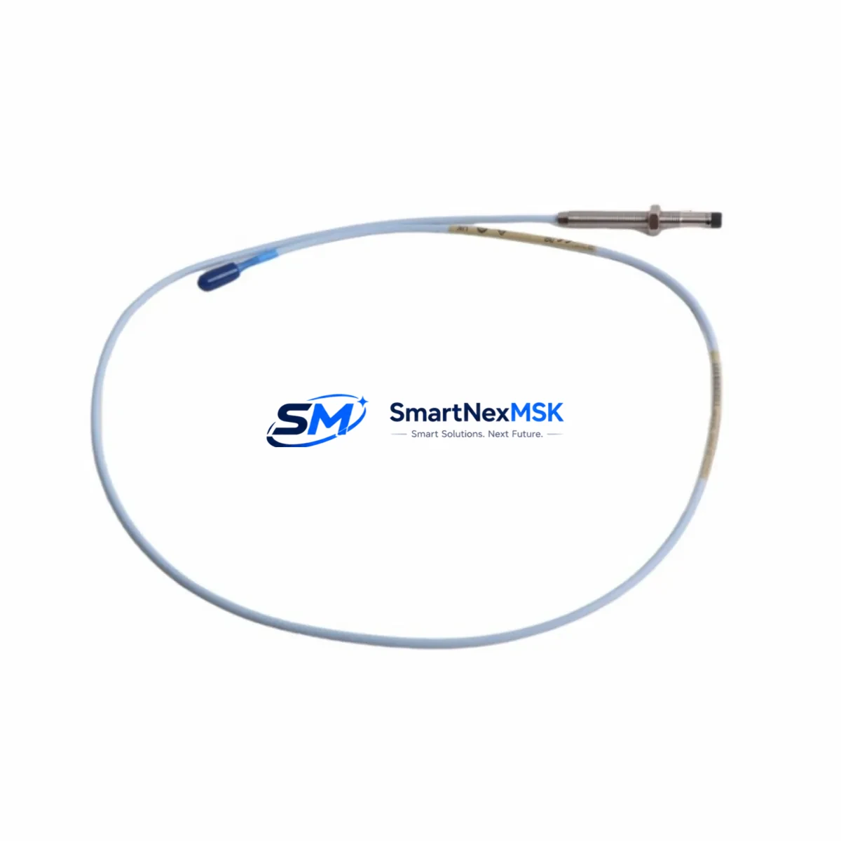
The Bently Nevada 330101-48-71-20-02-05 is an 8mm eddy-current proximity transducer engineered for the 3300 XL Series machinery protection and condition monitoring platform. As legacy rotating machinery assets continue operating well beyond their original design life, the demand for verified drop-in replacements and retrofit-compatible components has never been higher. This transducer is stocked and tested to serve as a direct functional replacement for discontinued or end-of-life units in turbine, compressor, pump, and motor protection applications across oil and gas, power generation, petrochemical, and heavy industrial facilities.
Whether you are restoring a failed channel in an existing 3300 XL rack, upgrading a brownfield control cabinet, or executing a planned outage replacement program, the 330101-48-71-20-02-05 integrates directly into your existing wiring infrastructure without requiring changes to the extension cable, proximitor, or monitor card configuration. The transducer operates on the standard Bently Nevada -24 VDC bias voltage supply and delivers a linear output range of -2 VDC to -18 VDC, fully compatible with the 3300 XL 8mm Proximitor® module and downstream signal conditioning cards such as the 3300/16 and 3300/20 series monitor cards.
Upgrade Compatibility Table
| Parameter | Detail |
|---|---|
| SKU / Part Number | 330101-48-71-20-02-05 |
| Series Compatibility | Bently Nevada 3300 XL 8mm Proximity System |
| Transducer Tip Diameter | 8 mm |
| Cable Length | 48 inches (1.2 m) integral cable |
| Connector Type | Standard BNC / coaxial, compatible with 330130 extension cable |
| Bias Voltage | -24 VDC (supplied by Proximitor) |
| Output Range | -2 VDC to -18 VDC linear |
| Installation | Direct retrofit — no bracket or wiring modification required |
| Compatible Proximitor | 3300 XL 8mm Proximitor® (e.g. 330180-91-00) |
| Compatible Monitor Cards | 3300/16, 3300/20, 3500/40M series |
| Communication / Protocol | Analog 4–20 mA / voltage output; compatible with DCS and safety system inputs |
| Replacement Recommendation | Direct drop-in for 330101-48-71-20-02-05 and functionally equivalent discontinued variants |
| Commissioning Note | Verify gap voltage at -10 VDC ±0.5 VDC at nominal air gap (1.0 mm for 8mm probe) |
| Warranty | 12 Months from date of shipment |
Retrofit Planning for Existing Automation Systems
Successful integration of the 330101-48-71-20-02-05 into an aging control system requires a structured pre-installation review. Begin by auditing the existing rack configuration: confirm the 3300 XL rack backplane is intact and that the Proximitor module slot is correctly addressed. In multi-channel racks, each Proximitor such as the 330180-91-00 must be individually verified for bias supply continuity before the new transducer is connected.
Extension cable integrity is a common failure point in retrofit projects. The 330130-080-00-00 extension cable (or equivalent 8m coaxial extension) should be inspected for shield continuity and connector corrosion before reuse. If the cable shows impedance deviation, replacement is recommended to avoid introducing noise into the measurement chain. The transducer, extension cable, and Proximitor form a matched system — substituting any single element without verifying the others can introduce calibration offset errors that trigger false alarms on the 3300/16 or 3300/20 monitor cards.
For facilities migrating from older 3300 series racks to the 3500 Series machinery protection system, the 330101-48-71-20-02-05 transducer remains compatible when paired with the appropriate 3500/40M proximitor I/O module. This migration path preserves the existing field wiring and sensor investment while enabling integration with modern DCS platforms, Modbus TCP/IP communication, and HART-enabled condition monitoring networks. During migration, the I/O module address must be reconfigured in the 3500 rack using System 1 Evolution software or the Rack Configuration Utility to match the new channel mapping.
Control cabinet upgrades often involve replacing the 3300 XL power supply module alongside the transducer. Confirm that the replacement power supply — typically a 3300/05 or equivalent — delivers stable -24 VDC under full rack load before energizing the new transducer. Voltage sag under load is a leading cause of premature transducer failure in retrofit scenarios. Additionally, verify that the HMI display screens configured in the existing SCADA or DCS system correctly reference the new channel tag names if any rack re-addressing has occurred during the upgrade.
For I/O expansion projects where additional vibration or position measurement points are being added to an existing 3300 XL rack, the 330101-48-71-20-02-05 can be deployed alongside thrust position transducers and differential expansion sensors within the same rack frame, provided sufficient Proximitor slots and power budget are available. Coordinate with the control system engineer to update the safety instrumented system (SIS) logic if the new measurement point feeds a trip or alarm function.
Downtime Control During System Migration
Minimizing unplanned downtime is the primary concern in any rotating machinery protection retrofit. The 330101-48-71-20-02-05 is pre-tested and shipped with a functional verification report, allowing installation teams to proceed directly to gap setting and commissioning without bench testing delays. To protect the original program logic during a 3300-to-3500 series migration, export and archive the existing rack configuration file from the System 1 or Rack Configuration Utility before making any hardware changes. This ensures that channel scaling, alarm setpoints, and trip logic can be restored exactly if a rollback is required.
During the physical swap, maintain control continuity by working channel-by-channel rather than replacing the entire rack simultaneously. Bypass the affected channel at the DCS or SIS level using the appropriate maintenance override, install and gap the new transducer, verify the output voltage, then release the bypass before proceeding to the next channel. This approach keeps the machine protected throughout the maintenance window and reduces the risk of a spurious trip caused by an open input channel.
For facilities with strict change management requirements, all wiring modifications, gap settings, and software configuration changes should be documented in the maintenance management system (CMMS) before the unit is returned to service. Our team provides pre-shipment functional test data for each 330101-48-71-20-02-05 unit to support your commissioning records and audit trail.
Retrofit Support FAQ
Q1: Is the 330101-48-71-20-02-05 a direct replacement for my existing unit without rewiring?
Yes. The 330101-48-71-20-02-05 uses the same integral cable length, connector type, and electrical specifications as the original Bently Nevada unit. No bracket modification or wiring change is required. Simply disconnect the old transducer from the extension cable, install the replacement at the same mounting position, set the air gap to the specified nominal value, and verify the bias voltage output at the Proximitor.
Q2: How do I verify compatibility with my existing 3300 XL Proximitor and monitor card?
Confirm that your installed Proximitor is rated for the 8mm probe system (e.g., 330180-91-00 or equivalent). Check the monitor card part number against the 3300 XL system documentation to confirm it accepts the -2 VDC to -18 VDC output range. If you are unsure, provide your rack configuration details to our technical team and we will confirm compatibility before shipment.
Q3: What commissioning steps are required after installation?
After mechanical installation, connect the transducer to the extension cable and power the Proximitor. Measure the DC output voltage at the Proximitor output terminals. At the nominal air gap (1.0 mm for 8mm probes), the output should read -10 VDC ±0.5 VDC. Adjust the mounting position to achieve this reading, then lock the transducer in place. Verify that the monitor card displays the correct gap value and that no fault or not-OK indicators are active before releasing the channel from maintenance bypass.
Q4: What warranty and post-shipment support is provided?
Every 330101-48-71-20-02-05 unit is covered by a 12-month warranty from the date of shipment. Each unit ships with a pre-shipment functional test report. If a unit fails within the warranty period under normal operating conditions, we will provide a replacement at no charge. Our technical support team is available to assist with installation questions, compatibility verification, and commissioning guidance throughout the warranty period.
© 2026 SMARTNEXMSK. All rights reserved.
Original Source: https://smartnexmsk.com
Contact: sales@smartnexmsk.com | +86 18259474341


