Bently Nevada 330102-00-08-50-02-CN 3300 XL Proximity Probe: Retrofit-Ready Replacement for Legacy Vibration Monitoring Systems
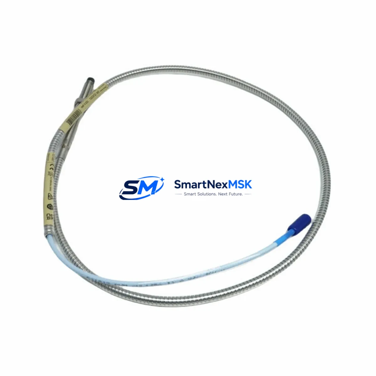
The Bently Nevada 330102-00-08-50-02-CN is an 8mm proximity probe engineered for the 3300 XL series continuous vibration monitoring platform. As aging machinery protection systems approach end-of-life or face discontinued spare parts availability, this probe serves as a direct retrofit solution for facilities operating legacy Bently Nevada 3300 series installations. Whether you are replacing a failed sensor on a critical rotating machine or executing a planned upgrade of your entire condition monitoring infrastructure, the 330102-00-08-50-02-CN delivers the dimensional accuracy, signal linearity, and environmental resilience required for uninterrupted plant operation.
This probe is designed to work within the complete 3300 XL proximity transducer system, which includes the companion extension cable (typically the 330130 series) and the proximitor sensor (such as the 3300 XL 8mm Proximitor, model 330180). When retrofitting an existing installation, engineers must verify that the total cable length — probe plus extension cable — matches the proximitor’s calibrated range. Mismatched cable lengths are one of the most common commissioning errors during legacy system upgrades and will result in incorrect gap voltage readings and false trip conditions.
Before removing the existing probe from service, document the current gap voltage at the operating shaft position. The standard installation gap for 8mm probes in the 3300 XL system is typically set to produce a –10 VDC output, corresponding to a physical gap of approximately 1.0 to 1.5 mm depending on target material. Record this value and use it as your baseline during reinstallation and recommissioning of the 330102-00-08-50-02-CN.
Upgrade Compatibility Table
| Parameter | Details |
|---|---|
| SKU / Part Number | 330102-00-08-50-02-CN |
| Brand / Series | Bently Nevada / 3300 XL |
| Probe Diameter | 8 mm |
| Cable Length | 0.5 m (probe body); total system length per proximitor calibration |
| Connector Type | Coaxial, compatible with 330130 series extension cables |
| Compatible Proximitor | 330180 (3300 XL 8mm Proximitor) |
| Compatible Monitors | 3300/16, 3300/20, 3300/25, 3500/42M, 3500/45 |
| Installation Requirement | Verify total cable length; set gap to –10 VDC baseline |
| Communication Compatibility | Analog signal (–24 VDC supply); compatible with 3500 rack Modbus/TCP and System 1 software |
| Replacement Recommendation | Direct drop-in for 330102-00-08-50-02-CN; verify target material (steel vs. non-ferrous) |
| Commissioning Focus | Gap voltage calibration, cable continuity check, proximitor output verification |
| Warranty | 12-Month Warranty — covers manufacturing defects and signal performance |
Retrofit Planning for Existing Automation Systems
Successful integration of the 330102-00-08-50-02-CN into an existing plant environment requires a structured approach to hardware compatibility, wiring verification, and software configuration. The following outlines the key considerations for engineers planning a retrofit or emergency replacement.
Power Supply and Signal Wiring: The 3300 XL proximity transducer system operates on a –24 VDC power supply, typically sourced from the monitor rack’s internal power module. When upgrading from an older 3300 series installation to a 3500 series rack — for example, migrating from a 3300/16 monitor to a 3500/42M dual-channel vibration monitor — verify that the new rack’s power budget accommodates all connected transducers. The 3500 rack power supply module (such as the 3500/15 Power Supply) must be sized for the total transducer load, including any newly added I/O modules or communication gateway cards.
Extension Cable and Connector Integrity: The 330130 series extension cables are the standard interconnect between the 330102-00-08-50-02-CN probe and the proximitor. During a retrofit, inspect all existing extension cable connectors for corrosion, mechanical damage, or impedance drift. A degraded extension cable will corrupt the probe’s linear output range even if the probe itself is new. Replace any suspect cables as part of the upgrade scope.
Backplane and Rack Slot Assignment: When installing the replacement probe into a 3500 series rack, confirm the monitor module’s slot address and channel assignment within the rack configuration software (Rack Configuration Software, or RCS). Each channel must be mapped to the correct transducer type, probe diameter, and cable length. Incorrect slot configuration is a frequent source of nuisance trips during post-retrofit commissioning. If the facility is also upgrading the I/O module — for instance, adding a 3500/40M proximitor I/O module — ensure the new module firmware is compatible with the existing rack’s backplane revision.
HMI and System 1 Integration: Facilities using Bently Nevada System 1 condition monitoring software must update the transducer database entry to reflect the new probe model and calibration constants. If the control room HMI displays real-time vibration trends via OPC-DA or OPC-UA from the 3500 rack, verify that the tag names and engineering unit scaling remain consistent after the probe swap. Any change in the proximitor’s scale factor — for example, switching from a 200 mV/mil to a 100 mV/mil output — will require corresponding updates in the DCS historian and alarm management system.
Communication Protocol Migration: Older 3300 series installations typically relied on hardwired 4–20 mA analog outputs to the DCS. Modern 3500 racks support Modbus/TCP and EtherNet/IP communication cards (such as the 3500/92 Communication Gateway), enabling digital integration with Emerson DeltaV, Honeywell Experion, or ABB 800xA control platforms. If the retrofit scope includes a protocol migration from analog to digital, plan for DCS I/O card changes, network switch port allocation, and firewall rule updates in the plant’s industrial network.
Programming and Logic Compatibility: Trip multiply and alarm setpoints stored in the 3500 monitor must be reviewed and re-entered after any hardware change. Export the existing configuration from RCS before beginning the retrofit, and use the exported file as the baseline for the new configuration. This preserves the original alarm philosophy and reduces the risk of setpoint errors during recommissioning.
Downtime Control During System Migration
Minimizing unplanned downtime is the primary operational concern when replacing proximity probes on critical rotating machinery. The following practices are recommended to protect production continuity during the migration of the 330102-00-08-50-02-CN into service.
Pre-Outage Preparation: Stage all replacement components — probe, extension cable, proximitor, and any required rack modules — at the work site before the planned outage window. Confirm that the 330102-00-08-50-02-CN has been bench-tested against a reference proximitor and that the output voltage at a known gap distance matches the published calibration curve. This pre-shipment functional test, which is included in our standard outgoing inspection, reduces the risk of discovering a defective component after the machine is already offline.
Parallel Verification: Where machine design permits, install the new probe alongside the existing probe before taking the machine offline. Use a portable oscilloscope or the monitor’s front-panel display to compare the output of the new 330102-00-08-50-02-CN against the existing sensor while the machine is running. This live comparison confirms probe orientation, gap setting, and signal quality before the cutover, and allows the maintenance team to identify any wiring errors without interrupting production.
Logic and Alarm Bypass Procedures: Coordinate with the control room to place the affected vibration channel in bypass mode within the 3500 monitor before disconnecting the existing probe. This prevents a spurious trip signal from propagating to the emergency shutdown system (ESD) or the DCS during the probe swap. Document the bypass activation and deactivation times in the plant’s management of change (MOC) record.
Post-Installation Verification: After installing the 330102-00-08-50-02-CN and reconnecting all cables, perform a full channel verification sequence: confirm gap voltage, check the OK relay status on the monitor front panel, verify alarm and danger setpoint annunciation using a test magnet or signal simulator, and confirm that the System 1 software is receiving a valid, trending signal. Only after all verification steps are complete should the bypass be removed and the channel returned to normal protection service.
Retrofit Support FAQ
Q1: Is the 330102-00-08-50-02-CN a direct replacement for older 330102 series probes?
Yes. The 330102-00-08-50-02-CN is dimensionally and electrically compatible with earlier 330102 variants used in 3300 series installations. The key difference is the CN suffix, which denotes a specific cable and connector configuration. Verify that the connector type on the existing extension cable matches before installation. If the existing extension cable uses an older connector standard, a 330130 series adapter or a full cable replacement may be required.
Q2: What wiring checks are required before commissioning?
Prior to energizing the system, perform a continuity check on the coaxial cable from the probe tip to the proximitor input. Verify shield continuity and confirm that there is no short circuit between the center conductor and the shield. Measure the DC resistance of the probe coil (typically 5–10 ohms for an 8mm probe) to confirm the probe is undamaged. After energizing, measure the gap voltage with the probe at the nominal installation gap and confirm it falls within the proximitor’s linear range (typically –2 VDC to –18 VDC).
Q3: How is compatibility with the 3500 rack verified before installation?
Download the current rack configuration from RCS and confirm that the monitor module assigned to the probe channel is configured for an 8mm proximity transducer with the correct cable length. Cross-reference the proximitor model number (330180 for standard 8mm applications) against the monitor module’s supported transducer list in the 3500 Series Rack Configuration and Utilities Guide. If the rack is being upgraded from a 3300 series monitor, a full rack reconfiguration will be required, including re-entry of all setpoints and I/O assignments.
Q4: What does the 12-month warranty cover, and what is the return process?
The 12-month warranty covers manufacturing defects, coil integrity, connector reliability, and signal output performance under normal operating conditions. It does not cover damage resulting from incorrect installation, overvoltage, or mechanical impact. To initiate a warranty claim, contact our sales team with the order number, a description of the observed fault, and the gap voltage and OK relay status at the time of failure. Replacement units are typically dispatched within 3–5 business days after fault confirmation.
© 2026 SMARTNEXMSK. All rights reserved.
Original Source: https://smartnexmsk.com
Contact: sales@smartnexmsk.com | +86 18259474341


